
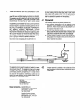
Technical data

7
REPLACEMENT OF COMPONENTS
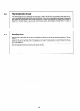
Before commencing any work involving component replacement :
1.
Isolate electrical supply.
2. Turn off gas at the gas service cock.
3. Turn off water at the water inlet cock.
4. Drain the appliance by opening hot water outlet tap and removing the drain plug in the water servlce cock.
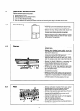
5. Remove the front casing (see Section 6.1).
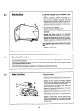
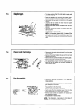
7.1
Thermocouple
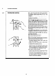
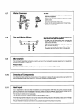
7.2
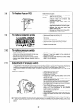
Spark Electrode
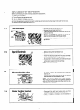
Thermoelectric valve
7.4
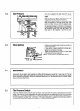
Water Section Venturi
-
Remove the burner (see Section 6.2).
-
Remove the pilot (see Section 6.31.
- Trace the thermocouple and disconnect at the ter-
minal on the PCB.
-
With a 7 mm boxspanner, unscrew the nut (B) hol-
ding the thermocouple into the gas section.
-
Thread the thermocouple and wire up through the
gas section.
-
Replace in reverse order.
- Remove the burner (see Section 6.2).
- Remove the electrode retaining screw (A).
-
Pull off the electrode cable from the piezo cartridge.
- Lift the electrode out of the gas section.
- Re-assemble in reverse order, and note that the slot
in the connector on the end of the electrode cable is
vertical when pushed onto the cartridge.
NOTE : Spark gap is 3-5 mm
-
To renew, remove the thermocouple conductor
lead nut (A).
-
Unscrew cap (B) from the side of the gas section
and withdraw the thermoelectric valve.
NOTE - This heater is fitted with a safety interlock.
When the pilot is turned off, the appliance cannot be
relit until the thermocouple cools down and the ligh-
ting sequence is repeated.
-
Disconnect the right hand heating body leg from
the water section and remove the venturi (A).
-
Clean or replace as necessary and re-assemble in
reverse order.
18
7.3