
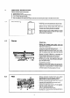
Technical data
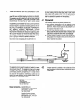
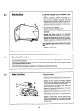
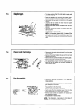

Water Governor
6.10
6.11
To clean
- Turn off the cold water
supplv
to the appliance and
drain into receptacle.
- Remove the governor situated in the base of the
water section.
- Clean the components with water.
- Check that the spring loaded piston moves freely.
- Replace in reverse oder.
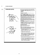
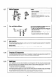
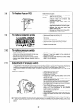
Gas and Water Filters
Gas and water inlet filters are fitted between the
inlet service cocks and the appliance.
- To clean, turn off the service cocks, unscrew the
union nuts attaching the cocks to the appliance
and remove the filters.
- Clean the filters by blowing or washing in water. DO
NOT USE ANY SOLVENTS.
- Replace ensuring that the coarse filter is fitted in
the water inlet and the fine filter in the gas inlet.
6.9
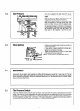
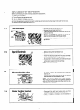
Microswitch
The microswitch operating mechanism is factory set and if the microswitch requires replacement or adjustment
proceed as in Section 7.12 and 7.13.
Pressure switch :
The pressure switch is factory set. To replace or adjust proceed as in Section 7.10 and 7.11
Greasing of Components
Care should be taken during the annual service of an appliance to grease the gas valve spindle (see Section 6.6)
and the diaphragm spindle tsee Section 7.5). Use either graphited or silicone grease.
Heat Input
It is a requirement of the Gas Safety (Installation and Use) Regulations 1984 that the burner pressure and gas
rate are checked each time an appliance is serviced, likewise the service engineer should satisfy himself with re-
gard to gas soundness and the adequacy of combustion and ventilation air if this is appropriate.
The heat input is preset and non-adjustable.
The heat input and burner pressure should be checked against Table 1.
If the heat input/burner pressure is not correct check the working pressure at the pressure test point on the gas
service cock. This should be 20 mbar (8 in wg).
The gas installation should be examined for any possible blockage if the pressure is incorrect.
17