CHAFFOTEAUX LIMITED BRITONY II FF G.C. No 52.980.
GENERAL 1. The BRITONYII FF is a fanned draught, balanced flued instantaneous multipoint appliance. The flue is suitable for rear outlet, or to either side. The maximum recommended flue length is 3 m. straight. The appliance is for connection to a mains cold water supply only. A permanent electrical connection is required and should be provided by use of a fused spur. The external electrical supply should be via a double pole switch having 3 mm. contact separation in both poles.
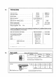
Technical Data 1.3 Heat input nominal . Heat output nominal . . . . . . . . . . Gas rate (maximum) . . . . . Burner pressure . . . . . . . . . . . . . . . . . . . . Burner pressure tolerance . Main burner injectors . . . .. Pilot injectors .. .. ........... Water flow rate - raised 50 ‘C (90 ‘F) . Water flow rate - raised 30 “C (54 “F) . Minimum operating head ......... Maximum operating head . .... . . Electrical Connections - 240 V 50 Hz supply fused 3 A. . .. . .. .. .. .. . . .. .. . 28.6 kW 22.
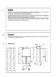
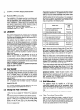
2. INSTALLATION REQUIREMENTS The appliance must be installed so that the flue terminal is exposed to external air. The appliance must NOT be installed so that the terminal discharges into another room or space such as an outhouse or lean-to. It is important that the position of the terminal allows a free passage of air across it all times. The minimum acceptable spacings from the terminal to obstructions and ventilation openings are specified in the following chart. 2.
2.7 Air supply The cable should be passed through the gland on the top of the appliance and the clamp tightened to secure the cable. Ensure current carrying conductors become taught before earthing conductor should cable slip from the cord anchorage. Connection to the appliance should be made in accordance with diagram (see section 3,6,2). The appliance does not require any purpose provided ventilation unless installed in a compartment.
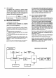
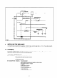
CIRCUITDIAGRAM L 2A Fig.
MICRO-SWITCH WATERFLOW PREBSURE SWITCH PRINTED CIRCUIT BOARD ,--w--w------- 11 Fig. 4 3. INSTALLING THE APPLIANCE A vertical flat area is required for the appliance : 1006 mm high x 445 mm wide (39.6 in x 17.5 in). The surface on which the appliance is mounted must be of a non combustible material. 3.1 Packaging The appliance is attached to the wall via the mounting bracket and two bottom screw fixings. The appliance is packed in a single carton. Remove contents from carton and check against list.
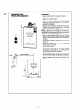
-. 3.2 Preparing and fitting the appliance Preparation : y--- 1 142 - 1: 142 j --c 197.5 mm minimum I 7. --rI !I I i - Remove the bottom trim by pulling forwards. - Slide the controls facia plate (PI upwards to disengage from retaining bracket. - Release the front case by removing the four fixing screws and washers positioned at the top, bottom and centre of appliance.
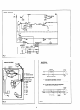
- Fitting the flue 3.3 D - - Gas Connection 3.4 Measure the wall thickness and cut flue duct and air inlet duct to required length, (see Section 1.4). Peel off protective paper from adhesive side of cork gasket (A) and place on mating side of flue turret(B) lining up screw holes and press down. Fit locking ring (C) and ‘0’ ring over the air inlet duct. Fit flue duct and turret so that it engages into the terminal.
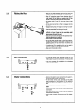
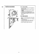
Electrical connections 3.6 3.6.1. Pressure Switch - Connect the wires at the top of the appliance to the pressure switch. - The grey wire is connected to normally closed (NC I) contact. - The pink wire to the normally open (NO 21contact. - The violet wire to the common (P) contact. - Fit the flue turret cover passing the wire through one of the slots provided and secure with the screws provided. - See figure. 3.6.2. Mains Connection - Pass 0.75 mm2 heat resisting cable through cable gland.
Do not use the appliance with push on hand showers that fit over existing hot and cold water taps or with mixer taps unless both supplies come from the same source. Showers forming part of bath mixers are not recommended for satisfactory operation of the appliance. APPLICATIONSOF THE BRITONY II FF The appliance is designed to serve a varietv of hot water draw off Points including washing machines and showers. The appliance can be connected to all hot water draw-off points in the installation.
5. 5. COMMISSIONING 5.1 Putting into Service 5.1.1. Open the gas and water service cocks beneath the appliance, purge the gas supply (CP331:3). Turn on an adjacent tap and purge the water side of the installation. Test for water soundness at all appliance and external pipework connections. Switch on electrical supplv, fan will run at low speed. 5.1.3. To light the pilot temporarily fit the gas control knob (A) and light the pilot by turning the knob 90’ anti-clockwise.
5.2 Gas Pressure - Turn on an adjacent hot water draw off, the appliance will now light and the fan will change to high Speed. - With the front case fitted, check the burner setting pressure at the pressure test point U. - If the burner setting pressure is not correct, check that the pressure at the gas service cock, test point is 20 mbar (8 in.w.g.) with the appliance operating. If the inlet pressure is not correct, check for any possible blockage or restriction in the pipework to the appliance.
5.6 Thermoelectric Circuit The Thermocouple Circuit is fitted with an interrupter so that if the air flow is not proved on high speed the circuit is incomplete and the flame failure device will operate.
6. SERVICING INSTRUCTIONS Before commencing any service work : 1. Isolate electrical supply. 2. Remove bottom trim by sliding forward. 3. Turn off gas at gas service cock. 4. Turn off water at water service cock. 5. Drain the appliance by opening hot water outlet tap and removing drain plug in the water service cock. 6.1 Front Casing To remove : - Pulloff gas control and temperature selector knobs. - Remove controls facia plate by sliding upwards.
Heating Body 6.4 a) The heat exhcanger can be examined in position : - Remove combustion chamber front panel as in Section 6.2 if not already removed. Prior to cleaning the heat exchanger adequate precaution should be taken to protect the pilot burner/gas valve assembly to prevent the ingress of dust etc. - If extensive cleaning is necessary, the heat exchanger will need to be removed asfollows. b) To remove heat exchanger - Slide out combustion lining and retain.
6.9 Water Governor To clean - Turn off the cold water supplv to the appliance and drain into receptacle. - Remove the governor situated in the base of the water section. - Clean the components with water. - Check that the spring loaded piston moves freely. - Replace in reverse oder. Gas and Water Filters Gas and water inlet filters are fitted between the inlet service cocks and the appliance.
7 REPLACEMENT OF COMPONENTS Before commencing any work involving component replacement : 1. Isolate electrical supply. 2. 3. 4. 5. Turn off gas at the gas service cock. Turn off water at the water inlet cock. Drain the appliance by opening hot water outlet tap and removing the drain plug in the water servlce cock. Remove the front casing (see Section 6.1). 7.1 Thermocouple - Remove the burner (see Section 6.2). - Remove the pilot (see Section 6.31.
Diaphragm - To renew ensure that the cold water supply and gas are turned off. - Drain the appliance by removing the water governor plug situated in the base of the water section. - ys;;ect the two water connections at the water - Unscrew the six screws (A) which hold the water section to the gas section. - Remove the water section complete with the diaphragm. - Carefully remove and inspect the plastic water section top cover. - Re-assemble in reverse order. NOTE : Fit the water govenor last.
7.8 To Replace Fuse or PCB Isolate electrical supply. (A) FUSE : - Pull out fuse holder (A) from board and slide fuse out of holder. (B) PCB : - Remove connections (fan. microswltch. pressure switch and ionisation lead complete with sleeve) - Disconnect mains sup~lv cable from termtnals. - Remove two nuts and washers (6) retaining thermocouple and conductor lead. - Remove fuse and ease board from plastic retaining clips. - Remove four screws and remove PCB. - Re-assemble in reverse order. l A 7.9 7.
7.12 Replacement of Microswitch 7.13 Adjustment - 7.14 of Microswitch operating mechanism Re-establish electrical supply - leave gas cock and hot water taps off. Set temperature selector to f. Slacken lock screw (B) using I,5 mm hexagon socket screw kev. Check whether fan is at high or low speed. If fan at low speed screw out adjustment screw (A) until high speed is obtained, then screw in until high Speed k observed then a further 3 full turns.
8 FAULT FINDING CHART FOR BRITONY II FF PROBLEM REMEDY CAUSE 8.1 Pilot does not light i) ii) iii) iv) Gas service cock closed Air in pipe Pilot injector blocked No ignition spark Dpen service cock Purge line Clean or change Check electrode, lead and ignitor 8.2 Poor Pilot Flame i) ii) iii) iv) v) Pilot injector dirty Wrong injector Pilot head blocked Faulty pilot tube Pilot injector loose Clean or change Change for correct diameter (0.23) Clean Clean or replace Tighten 8.
8 FAULT FINDING CHART FOR BRITONY II FF PROBLEM REMEDY CAUSE 8.5 Explosive Ignition i) Pilot too small ii) Slow ignition not adjusted Check pilot tube and injector Check and adjust (see 5.3) 8.6 Gas control tap stiff (User’s) i) Grease dried ii) Operating mechanism replaced incorrectly Clean and regrease 8.7 Low Water Temperature i) ii) iii) iv) v) 8.
Chaffoteaux Ltd, Concord House, Brighton Road, Salfords, Redhill, Surrey RHI 5DX. Telephone : Harley (0293) 772744. Telex : 87378. Warrington (0925) 830052.