
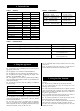
Technical data

A
G
D
H I
F
J
E
A
B C
G
M
F
F
L
L
K
K
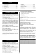
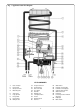
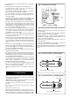
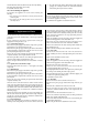
Fig. 3. Siting of the flue terminal.
MINIMUM SITING DIMENSIONS FOR POSITIONING THE BALANCED
FLUE TERMINAL
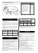
6.1 The appliance does not require a separate vent for
combustion air.
6.2 Installations in cupboards or compartments require
permanent vents for cooling purposes (one at high level and one
at low level) either direct to outside air or to a room. Both vents
must pass to the same room or be on the same wall to the
outside air.
6.3 There must be sufficient clearance around the appliance to
allow proper circulation of ventilation air. The clearances
required for installation and servicing will normally be adequate
for ventilation.
6.4 The minimum free areas required are given below.
6. Air Supply
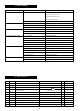
TOTAL LENGTH OF
GAS SUPPLY PIPE (metres)
369
Gas Discharge Rate (m
3
/h)
2.9 – – 15
8.7 5.8 4.6 22
18.0 12.0 9.4 28
Pipe
Diameter
(mm)
Position of Air from Air direct
air vents the room from outside
High Level 270 cm
2
. 135 cm
2
.
(42 in
2
.) (21 in
2
)
Low Level 270 cm
2
. 135 cm
2
.
(42 in
2
.) (21 in
2
.)
6.5 Refer to BS 6798 and BS 5440:2 for additional information.
The appliance requires 2.7 m
3
/hr (95.4 ft
3
/hr) of gas. The gas
meter and supply pipes must be capable of supplying this
quantity of gas in addition to the demand from any other
appliances being served. The following table gives an indication
of limiting gas pipe lengths and the allowance to be made for
fittings. Refer to BS 6891 for further information.
The meter governor should deliver a dynamic pressure of 20
mbar (8 in w.g.) at the appliance.
The complete installation, including the gas meter, must be
tested for soundness and purged. Refer to BS 6891.
A gas service cock must be fitted before each appliance, a gas
service cock is supplied with every natural gas appliance (not
supplied with LPG model).
Important: If the 2.7m
3
/hr gas rate to the appliance cannot be
reached, the specified hot water conditions will not be achieved.
This could result in customer complaints. Always ensure that the
gas supply is adequate.
7. Gas Supply
Note: Each fitting used in the gas line from the meter is
equivalent to a length of straight pipe which must be added to
the straight pipe length to give the total length.
i.e. Elbow=0.5 metres, Tee=0.5 metres, 90˚ bend=0.3 metres.
The installation must be carried out by competent persons.
On delivery, check to make sure that the packaging has not been
damaged. If there is evidence of damage, contact your supplier
immediately.
Check the 10 digit code number on the appliance carton to
ensure that the correct appliance for the gas supply has been
supplied.
The code number for a natural gas appliance is 7 702 340 006.
The code number for an LPG appliance is 7 702 440 007.
Before commencing work, check that the correct flue kit has
been supplied. There are three different telescopic flue kits
available for various wall thicknesses.
(See Technical Data – Table 2)
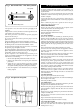
8.1 FLUE KIT INSTALLATION
Refer to flue kit installation instructions which are packed inside
the flue kit carton.
8.2 APPLIANCE INSTALLATION
(a) Unpack the appliance and take care to remove the installation
kit which is packed on top of the polystyrene packing.
The installation kit consists of the following:
One gas service cock (not supplied with LPG model)
One cold water isolating cock complete with fibre washer
One hot water outlet complete with fibre washer
Two 15 mm x
1
/2 in. BSP female copper compression fittings
8. Installation
6
TERMINAL POSITION MIN. DISTANCE
A– directly below an openable window or
other opening e.g. air brick. 300 mm (12 in.)
B– Below gutters, soil pipes or drain pipes. 300 mm (12 in.)
C– Below eaves. 300 mm (12 in.)
D– Below balconies or car port roof. 600 mm (24 in.)
E– From vertical drain pipes and soil pipes. 75 mm (3 in.)
F– From internal or external corners. 600 mm (24 in.)
G– Above ground, roof or balcony level. 300 mm (12 in.)
H– From a surface facing a terminal. 600 mm (24 in.)
I– From a terminal facing a terminal 600 mm (24 in.)
J– From an opening in a car port (e.g. door
window) into dwelling. 1200 mm (47 in.)
K– Vertically from a terminal on the same
wall. 1500 mm (60 in.)
L– Horizontally from a terminal on the same
wall. 300 mm (12 in.)
M– From door, window or air vent (achieve
where possible). 300 mm (12 in.)