
Technical data
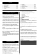
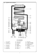
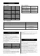
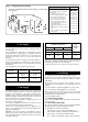
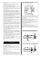
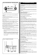
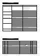

TABLE 1 – GENERAL
3. Technical Data
TABLE 2 – FLUE DETAILS
TABLE 3 – PERFORMANCE
4.1 The appliance may be installed in any room which has an
appropriate outside wall.
4.2 The appliance is not suitable for external installation.
4.3 The appliance does not require any special wall protection.
4.4 The wall must be capable of supporting the weight of the
appliance. See Technical Data – Table 1.
4.5 If the appliance is to be fitted in a timber framed building,
refer to the British Gas Publication “Guide for gas installations in
timber framed housing”.
4.6 The following clearances must be available for installation
and for servicing:
4. Siting the Appliance
4.9 No combustible surface must be within 75 mm of the casing.
See BS 476:4.
4.10 The distance between the inner face of a cupboard door
and the cabinet front should not be less than 75 mm.
Natural Gas LPG
Minimum rated output 7 kW 7 kW
Maximum rated output 21.4 kW 21.4 kW
Rated input 25.5 kW 25.5 kW
Gas rate (maximum) 2.7 m
3
/hr 2.0 m
3
/hr
Number of injectors 14 14
Injector diameter 1.10 mm 0.74 mm
Pilot injector marking 5 49
Burner pressure 17 mbar 27 mbar
Height 755 mm 755 mm
Width 400 mm 400 mm
Depth 220 mm 220 mm
Dry weight 16 kg 16 kg
Gas connection Rc
1
/2 Rc
1
/2
Hot/cold water connections 15 mm copper 15 mm copper
Wall hole size – width 224 mm (9 in.)
Wall hole size – height 326 mm (13 in.)
Standard flue – minimum length 260 mm (10.4 in.)
Standard flue – maximum length 430 mm (17.2 in.)
Short flue – minimum length 100 mm (4 in.)
Short flue – maximum length 150 mm (6 in.)
Extended flue – minimum length 410 mm (16.4 in.)
Extended flue – maximum length 570 mm (22.8 in.)
Maximum cold water supply inlet pressure 12 bar (180 p.s.i.)
Minimum cold water supply inlet pressure to operate the appliance 0.1 bar (1.5 p.s.i.)
Minimum cold water supply inlet pressure for maximum domestic hot water flow 1.0 bar (15 p.s.i.)
Domestic hot water delivery with temperature control knob fully anticlockwise 4 to 12.3 litres/minute at
25°C temperature rise
Domestic hot water delivery with temperature control knob fully clockwise 2 to 6.1 litres/minute at
50°C temperature rise
See Fig. 3.
5.1 The flue must be installed as specified in BS 5440:Part 1.
5.2 The terminal must not cause an obstruction nor the
discharge cause a nuisance.
5.3 If the terminal is fitted within 850 mm of a plastic or painted
gutter or within 450 mm of painted eaves then an aluminium
shield at least 750 mm long should be fitted to the underside of
the gutter or painted surface.
5.4 If a terminal is fitted less than 2 metres above a surface to
which people have access then a guard must be fitted.
5.5 The terminal guard must be evenly spaced about the flue
terminal and fixed to the wall using plated screws.
5.6 In certain weather conditions a terminal may steam and
siting where this could cause a nuisance should be avoided.
5.7 Take care to ensure that combustion products do not enter
ventilated roof voids.
5. Siting the Flue Terminal
4.7 The appliance can be installed in a cupboard used for airing
clothes provided that the requirements of BS 6798 and BS
5440:2 are strictly followed.
4.8 The airing space must be separated from the appliance
space by a perforated non-combustible partition. Expanded
metal or rigid wire mesh are acceptable provided that the major
dimension is less than 13 mm. See BS 6798:1987.
Above 50 mm
In front 600 mm
Below 150 mm
Right hand side 10 mm
Left hand side 10 mm
5