
Technical data
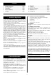
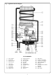
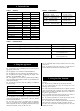
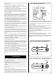
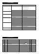

Fig. 1. Appliance water flow diagram
1. Heat exchanger
2. Pilot gas pipe
3. Gas injector nozzle
4. Measuring point
6. Valve spring
7. Large gas valve
8. Pilot gas filter
9. Pilot gas valve
10. Main gas valve
11. Pilot gas valve stem
12. Pilot gas button
13. Gas control slide
14. Piezo igniter
15. Gas filter
16. Magnetic unit
17. Slow-ignition valve
18. Venturi
19. Measuring point
20. Gas inlet
21. Water strainer
22. Hot water connecting pipe
23. Cold water connecting pipe
24. Volumetric water governor
25. Water flow selector
26. Relief valve
27. Correcting screw for minimum
water flow
28. Diaphragm
29. Blow-off valve
3
KEY TO COMPONENTS