OPERATION & MAINTENANCE MANUAL CSC Series Coolant Service Center Manual P/N 035-80318-00
Introduction The CSC10R is a time saving member of RTI's family of coolant handling equipment. This portable unit safely drains and refills automotive engine cooling systems in a portion of the time it takes for conventional methods. When properly operated, this unit induces no air or pressure into the engine's cooling system. No hose cutting or tee is required - gravity and the engine's own water pump perform the service.
Safety Precautions | WARNING: FAILURE TO FOLLOW THESE PRECAUTIONS CAN RESULT IN SERIOUS INJURY OR DEATH. ` Read and understand the operation manual completely before operating this unit. ` Always wear proper eye and skin protection when operating and maintaining this equipment. ` Hazardous voltages present. Use only with a grounded electrical outlet and grounded extension cords. Do not remove the ground prong from the plug. ` Take precautions to keep clothing, hair, hands, hoses, etc.
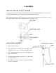
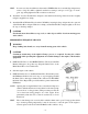
Assembly INSTALLATION OF SWIVEL CASTERS Locate the 4 swivel casters and bag of hardware that were shipped in the Fill Bucket on top of the unit. Verify that the hardware bag contains 8 bolts, 8 lock-washers, and 8 nuts. Have a helper tilt the unit on its bottom edge to install each caster. Insert the bolt from the top, secure the washer and nut on the bottom. Tighten with a 1/2" wrench or socket. HAND PUMP ASSEMBLY 1. Remove pump from box. 2. Screw barbed hose assembly onto the pump outlet.
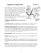
Sequence of Operation The CSC10R is a device designed to perform quick and simple engine coolant changes on automobiles and light trucks. When properly operated, this Quick Change can be accomplished in as little as ten minutes. The following is the normal sequence of operation for the CSC10R. Refer to the "Performing A Quick Change" and "Using The Recycling Center" section of this manual for complete instructions before operating your unit.
Performing A Quick Change Following these guidelines will allow a Quick Change on most vehicles. Due to the variety of automobile and light truck coolant system designs, slight variations of this procedure may be necessary. PREPARE FOR OPERATION 1. Pull the vehicle into the service area. Set the vehicle's heater controls to the highest temperature setting and turn off the heater fan. 2. SHUT OFF THE VEHICLE'S ENGINE and raise the hood. 3.
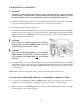
USE OF THE EVACUATION PUMP: | WARNING: Automotive cooling systems can be under pressure and extremely hot. Allow the vehicle's cooling system to cool down and use extreme caution when removing caps and hoses. Consult the vehicle manufacturer for recommended procedure on removing the radiator cap. 1. Squeeze the vehicle's upper radiator hose to determine the amount of pressure in the system. If the hose is hot and hard, allow the cooling system to cool down before proceeding. 2.
3. Attach the BLACK Drain Hose from the CSC10R to the removed, open end of the UPPER radiator hose by inserting its Step Adapter into the UPPER radiator hose. With a hose clamp, seal the UPPER radiator hose tightly to the "best fit" step on the Step Adapter. HINT: In some cases, the size difference between the UPPER radiator hose and the Step Adapter may seem too large. It is OK to tighten down the hose clamp to seal up to a 1/4" gap. A "worm-gear" type clamp tightened with a nut driver works best. 4.
HINT: In some cases, the size difference between the UPPER radiator hose and the Step Adapter may seem too large. It is OK to tighten down the hose clamp to seal up to a 1/4" gap. A "wormgear" type clamp tightened with a nut driver works best. 4. Attach the "best fit" Flexible Hose Adapter to the thermostat housing's inlet and secure it tightly using the supplied hose clamp. 5. Attach the BLACK Drain Hose from the CSC10R by inserting its Step Adapter into the open end of the Flexible Hose Adapter.
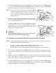
4. CLOSE the Fill Valve on the Green Hose. 5. Allow the engine to run for 10 seconds after closing the Fill Valve, then TURN THE ENGINE OFF. This lowers the coolant level in the radiator to help prevent coolant from spilling when re-attaching the UPPER radiator hose. | CAUTION: Failure to turn vehicles engine off ten seconds after closing Fill Valve can result in damage to the vehicle. 6. CLOSE the Drain Valve on the BLACK Drain Hose. 7. Remove the CSC10R from the vehicle.
Using The Recycling Center (Optional) The Coolant Recycling Center is located on the back of the CSC10R. Recycle when the Waste Coolant Drum contains between 12 and 15 gallons. Do not allow drum to overflow. | CAUTION: Waste coolant MUST be evaluated prior to recycling. Improperly recycled coolant which does not meet standards can result in damage to the equipment or the vehicle's engine and is not supported under warranty. | CAUTION: Do not recycle hot coolant. the waste coolant must be below 1200F.
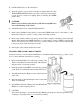
START THE RECYCLING PROCESS: 1. Plug the electric cord into a 115 volt, 60 Hz, grounded receptacle. Use a 16 gauge (minimum) grounded extension cord if necessary. 2. Open the Valve on the CSC10R YELLOW Hose and insert the hose into the small opening of the Clean Coolant Drum (extra 15 gallon drum supplied with the unit). 3. Press the Process Switch to the ON position at the Recycling Center (rear of unit) to start the Recycling Pump. 4.
3. Add 4 fluid ounces of Automotive Reinhibitor For CSC10R for each gallon of processed coolant. Mix well, by placing hose from hand pump into small opening on drum and recirculating. 4. After adding the initial amount of reinhibitor, measure the pH of the processed coolant using the pH Dip Sticks (supplied) or a pH meter. The desired pH is between 9.2 and 10.6. 5. If the measured pH is below this range, add additional 1 fluid ounce of reinhibitor per gallon of processed coolant and mix well.
NOTE: This step is important to ensure proper filter seal. Make sure the O-ring is sealed level in the groove in the housing. NOTE: If the O-ring appears damaged or crimped, replace it at this time. 6. Insert a new Filter Cartridge into the housing making sure that it slips down over the sump standpipe. Be certain that the 25 micron filter is installed in the left housing, and the 5 micron filter is installed in the right housing. 7. Screw housing onto the cap and hand tighten. DO NOT OVER TIGHTEN.
Coolant Service Center/Recycler Parts List Item Description 1 2 3 4&5 6 7* 8* 9* 10 11 12 13 14 15 16 18* 19* Filter Outlet Hose Assembly On/Off Switch Filter Housing 20 pc Filter Pack (10) 25 & (10) 5 Micron Filter Pump & Motor Assembly pH Measuring Sticks CSC10R Reinhibitor Filter Housing Wrench Fill Bucket Step Adapter Ball Valve Plastic Wand RED Pump Hose BLACK Drain Hose GREEN Fill Hose Pump Impeller Kit Evacuation Pump & Motor Assembly * Items Not Shown on Drawing - 14 - Part Number 070-80008-00
FREEZE POINT ADJUSTMENT CHART STEP 1 - CHECK FREEZE POINT OF PROCESSES COOLANT STEP 2 - DETERMINE NUMBER OF GALLONS OF PROCESSED COOLANT IN CLEAN COOLANT DRUM. THE DRUM HAS GALLON MARKINGS ON THE SIDE. STEP 3 - ADJUST FREEZE POINT TO -340F BY ADDING REQUIRED QUARTS OF ANTIFREEZE USING THE CHART BELOW. STEP 4- ADD PROPER AMOUNT OF REINHIBITOR PER INSTRUCTIONS ON BOTTLE LABEL OR MANUAL. GALLONS OF PROCESSED COOLANT FREEZE POINT 3 GALLONS 6 GALLONS 9 GALLONS 12 GALLONS 15 GALLONS -250F 1.8 1.