Hub Arm Assembly RTI TECHNOLOGIES, INC. York, PA 17402 800-468-2321 (ext.
Table of Contents 1 Introduction . . . . . . . . . . . . . . . . . . . . . . . . . . . . . . . . . . . . 1 2 Safety . . . . . . . . . . . . . . . . . . . . . . . . . . . . . . . . . . . . . . . . 2 3 Material List . . . . . . . . . . . . . . . . . . . . . . . . . . . . . . . . . . . . 3 4 Mounting of Hub & Centering Plate Storage Bracket . . . . 4 5 Component Storage . . . . . . . . . . . . . . . . . . . . . . . . . . . . . 5 6 Mounting the Cranks on the Centering Plate . . . . . . . . . .
1 Introduction Thank you for your purchase of a Lathe and Hub Arm Assembly. Congratulations on your choice! The BRC Lathe and Hub Arm Assembly is designed to outperform every other comparable hub mounted brake lathe in all respects. The BRC was designed as a completely new product. The special hub adaption method designed by RTI for the BRC is brand new and substantially improved. The BRC is designed to be easy to use.
2 Safety A. Avoid a major injury because of an unexpected start-up! Be sure that the BRC is not plugged in and supplied with electrical power when the lathe in not operating. This is particularly important when mounting the unit and performing the compensation adjustments. In addition, the BRC has an Emergency Stop button on the spindle drive motor. B. Avoid a major injury from rotating machinery! The BRC has a spindle motor with a great deal of power and torque.
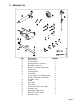
3 Material List Item A B C D E F G H I J K L M N O P Q R S Description Arm Assembly Hub Assembly Storage Bracket - Hub Arm Bolt (M10 -1.25 x 15) Washer 11mm (ID x 20mm OD) Square Nut Centering Plate Tommy Bar Crank - 90mm (Incl. Adjusting Nut) Washer (10mm ID x 19mm OD) Nut (M10 -1.25) U-Bolt Rear Plate Front Plate Washer (8mm ID x 16mm OD) Nut (M8 -1.
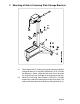
4 Mounting of Hub & Centering Plate Storage Brackets 4.1 Place Square Nut (F) inside each leg and mount the Hub Arm Storage Bracket (C) using Bolts and Washers (D-E). Position the bracket as shown, noting that the ends are cut to match the angle of each leg. Place plastic end cap into end of legs. 4.2 Mount the Centering Plate Bracket (L-M-N-O-P). Position bracket at the top of the lower column of the Drive Stand. The hook should face towards the Hub Arm Storage Bracket (C).
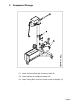
5 Component Storage 5.1 Store Centering Plate with Cranks on hook (A). 5.2 Store Hub Arm Assembly on bracket (B) 5.3 Store Tommy Bars and extra Cranks in box on bracket (C).
6 Mounting the Cranks on the Centering Plate 6.1 A scribe mark (A) is located on each Crank and large nut. Turn the large nut onto the Crank as far as possible, finger tight. The scribe mark should be aligned on the large nut and the barrel of the Crank. Then, loosen the large nut one full turn, once again aligning the scribe marks. Do this on all Cranks. 6.2 Numbers (B) are stamped on the Centering Plate next to the holes for mounting the Cranks.
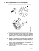
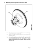
7 Mounting Centering Plate to the Wheel Hub 7.1 Place the large holes in the legs of the Cranks over the wheel lugs and install the lug nuts (A) finger tight. 7.2 Tighten the lug nuts to the manufacturer’s recommended wheel installation torque. 7.3 Place the Vibration Dampener Rubber Ring (B - supplied with BRC Lathe Assembly) around the rotor. Other types of vibration dampeners can also be used.
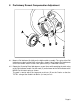
8 Preliminary Runout Compensation Adjustment 8.1 Mount a Dial Indicator (A) rigidly on the hub knuckle assembly. The stylus of the Dial Indicator must be in contact with surface B as shown. Lightly tap the Dial Indicator to ensure the needle returns to the same spot to verify it is mounted securely. 8.2 Rotate the Centering Plate 360 degrees several times while watching the total swing of the Dial Indicator needle.
8 Preliminary Runout Compensation Adjustment (Continued) 8.3 Rotate the Centering Plate until the Dial Indicator needle is at the largest number of the total swing, as shown. 8.4 Nuts on the two cranks are next adjusted to move the needle one-half the distance between the present reading and the mark on the bezel. 8.4.1 Slightly turn (1/16 rotation or less) small nut A in direction of arrow. 8.4.2 Tighten large nut B by turning in direction of arrow. 8.4.
9 Mounting the Hub Arm 9.1 Lift the Hub Arm Assembly (A) and carefully insert the threaded end into the Centering Plate (B). Turn the Centering Plate clockwise as indicated above until just tight. DO NOT use the Tommy Bars to tighten. 9.2 Slide the Adjustable Support Cane (C) onto the Pin (D).The Hub Arm Assembly can be rotated 360 degrees to allow the best access for cutting the rotor. 9.3 Extend the Adjustable Support Cane using Locking Handle (E) to support the Hub Arm Assembly.
10 Mounting the Lathe Head 10.1 Loosen Socket Hex Bolts (A) and slide the Lathe Head into the slots as shown above. Finger tighten the Socket Hex Bolts. 10.2 Loosen Locking Handles (C) and slide the Tube (B) to center the Lathe Head on the Rotor. 10.3 Continue adjusting the Tube (B) and the Lathe Head until the cutting tips are centered on the Rotor. 10.
11 Attaching the Drive Motor Note: The above shows a cut-away of the Hub Arm Assembly to illustrate the connection between the Drive Motor Shaft and the Pin and Ball in the Hub Arm Assembly. 11.1 Adjust the Drive Motor Stand so the Motor Shaft (A) is aligned with the hole in the Hub Arm Assembly. 11.2 Slide the Shaft (A) of the Drive Motor into the Hub Arm Assembly. It may be necessary to turn the shaft to align the slot in the end fitting with the pin (B) in the Hub Arm Assembly. 11.
12 Connecting Power Note: The above shows the completed set-up of the Hub Arm Assembly, Lathe Head, and Drive Motor. 12.1 Push in the Emergency Stop Button on the Drive Motor Control Box. 12.2 Connect the Power Cord (A) to an appropriately grounded power source. 12.3 Connect the Coiled Cord (B) from the socket on the side of the Drive Motor Control to the socket on top of the Lathe Head.
13 Final Runout Compensation Adjustment 13.1 Mount a Dial Indicator (A) rigidly on the hub knuckle assembly. The stylus of the Dial Indicator must be in contact with surface B as shown. Lightly tap the Dial Indicator to ensure the needle returns to the same spot to verify it is mounted securely. 13.2 Manually rotate the rotor several revolutions and observe the total runout as indicated on the Dial Indicator. 13.
14 Removing Hub Arm Assembly 14.1 Insert Tommy Bars (A) as shown above. 14.2 Rotate Tommy Bars as shown to release Hub Arm Assembly from the Centering Plate.