PORT POWERED INSERTION READER TECHNICAL REFERENCE MANUAL Manual Part Number 99875129 Rev 18 MAY 2009 REGISTERED TO ISO 9001:2000 1710 Apollo Court Seal Beach, CA 90740 Phone: (562) 546-6400 FAX: (562) 546-6301 Technical Support: (651) 415-6800 www.magtek.
Copyright© 1998-2009 MagTek®, Inc. Printed in the United States of America Information in this document is subject to change without notice. No part of this document may be reproduced or transmitted in any form or by any means, electronic or mechanical, for any purpose, without the express written permission of MagTek, Inc. MagTek is a registered trademark of MagTek, Inc.
LIMITED WARRANTY MagTek warrants that the products sold pursuant to this Agreement will perform in accordance with MagTek’s published specifications. This warranty shall be provided only for a period of one year from the date of the shipment of the product from MagTek (the “Warranty Period”). This warranty shall apply only to the “Buyer” (the original purchaser, unless that entity resells the product as authorized by MagTek, in which event this warranty shall apply only to the first repurchaser).
FCC WARNING STATEMENT This equipment has been tested and was found to comply with the limits for a Class B digital device pursuant to Part 15 of FCC Rules. These limits are designed to provide reasonable protection against harmful interference when the equipment is operated in a residential environment. This equipment generates, uses, and can radiate radio frequency energy and, if not installed and used in accordance with the instruction manual, may cause harmful interference with radio communications.
TABLE OF CONTENTS SECTION 1. FEATURES AND SPECIFICATIONS----------------------------------------------------------------------1 FEATURES............................................................................................................................................... 1 CONFIGURATIONS ................................................................................................................................. 2 MODES OF OPERATION ................................................................
Figure 1-1.
SECTION 1. FEATURES AND SPECIFICATIONS The Port Powered Insertion Reader can be single or dual head configuration. Figure 1-1 shows the Reader, the card orientation, and two bezel configurations. The dual head configuration can read the card on insertion and removal with the magnetic stripe facing up or down. The single head configuration can read the card on insertion and removal if the stripe is oriented to match the position of the head.
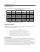
Port Powered Insertion Reader CONFIGURATIONS Table 1-1 lists the part numbers, single or dual head, head positions, and bezel types. Table 1-1.
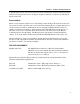
Section 1. Features and Specifications In the unbuffered mode, data can be retrieved from the card after the card has been inserted and while it is blocking the rear sensor. Issuing an “Inquiry Command” (see Section 3) will retrieve data from the card. Buffered Mode When a card is inserted and removed, a read attempt is made during both insertion and removal.
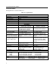
Port Powered Insertion Reader SPECIFICATIONS The Specifications are listed in Table 1-2. Table 1-2.
Section 1. Features and Specifications ENVIRONMENTAL Printed Circuit Board 21063608 (discontinued) Temperature Operating Units shipped prior to Nov 1, 2003: 32 oF to 131 oF (0 oC to 55 oC) Printed Circuit Board 21063619 or 21063550 -40°F to 158°F (-40°C to 70°C) Units shipped after Nov 1, 2003: -4 oF to 158 oF (-20 oC to 70 oC) Storage Humidity Operating Storage -40 oF to 176 oF (-40 oC to 80 oC) -40oF to 176oF (-40oC to 80oC) 10% to 90% noncondensing Up to 100% noncondensing * The 3.
Port Powered Insertion Reader 6
SECTION 2. INSTALLATION This section describes cabling information, mounting dimensions and PCB layout. The installation consists of mounting the Reader and connecting the cable. The head may be on top of the PCB, under the PCB, or if the unit has dual heads, both. The head, or heads, are installed in the factory to customer specifications. CONNECTORS The connector pin list is shown in Table 2-1. The mating connector for J4 is Molex 51021-0400. The terminals are Molex 50058-8000. Table 2-1.
Port Powered Insertion Reader MOUNTING Figure 2-1 shows the dimensions for mounting when using a flat-faced MagTek Bezel. Figure 2-2 shows the dimensions for mounting when using an extended MagTek Bezel. In these configurations, the top view and the side view show the head mounted under the PCB with connector J2 used. Note that for newer units (using PCB 21063619), the printed circuit board is reduced in size from that shown, and the location of J4 is shifted.
Section 2. Installation of Bezel Figure 2-1.
Port Powered Insertion Reader .5 .72 .830 3.35 Figure 2-2.
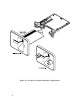
Section 2. Installation Figure 2-3. Board Layout and Cable Connections Note As shown in Figure 2-3, there is also a cable with a tie wrap, which may add to the length of the unit. If used as shown, approximately 0.25 inch is added to the length of the unit.
Port Powered Insertion Reader CARD INSERTION AND ORIENTATION The Reader can be mounted in two positions as shown in Figure 2-4. On the left panel of the illustration, the card is inserted with the magnetic stripe to the left. On the right panel of the illustration, the card is inserted with the magnetic stripe up. These are the mounting positions that permit any foreign object inserted into the slot to drop out of the reader.
SECTION 3. COMMANDS, FORMATS, TIMING This section includes commands, message formats, and transmission timing. The MagTek Device Drivers for Windows, part number 30037385, may be used with the Port Powered Insertion Reader. When these drivers are used, refer to MagTek Device Driver for Windows, Programming Reference Manual, Part Number 99875125. When power is applied, the Reader transmits a sign-on ID message.
Port Powered Insertion Reader Table 3-2. Options and Reader Responses COMMAND PREFIX (0x1B) (0x1B) (0x1B) (0x1B) (0x1B) TO SET OPTION S (0x53) E (0x45) C (0x43) P (0x50) B (0x42) TO CLEAR OPTION (DEFAULT) s (0x73) e (0x65) c (0x63) p (0x70) b (0x62) READER FUNCTION Send STX Send ETX Send CR Send ESC Buffered Mode Note If DTR is dropped and restored, the setup options are returned to the default state.
Section 3. Commands, Formats, Timing Where SS Data = = ES = Sensor = Start Sentinel: "%" for Track 1; ";" for Track 2; "+" for Track 3 Track Data in track order that is, Track 1 then Track 2 or Track 2 then Track 3 End Sentinel: "?" "0" no card in reader "1" card present in reader (rear sensor blocked) If there is an error in one of the tracks, the "Track Data" field will be replaced with "E" (0x45).
Port Powered Insertion Reader TIMING FOR ID SIGN-ON AND TRANSMISSION BURSTS Timing for the ID Sign-on and transmission bursts (5 ms with 10 ms between bursts) are shown in Figure 3-1. DTR ss 150 ms Sign-on ID ss ss Transmission Burst 5 ms 10 ms NOT TO SCALE Figure 3-1. Timing For ID Sign-on and Transmission Bursts. The firmware controls the operation of ID Sign-on and Transmission bursts.
Section 3. Commands, Formats, Timing TRANSMISSIONS EXAMPLES The following tables show transmission examples: Table 3-3.
Port Powered Insertion Reader 18
APPENDIX A. OPTIONAL FIRMWARE FEATURES JIS PORT POWERED INSERT READER Port Powered Insert Reader part number 21065131 (using firmware 21088827) supports both ISO and JIS card reading. By default, it reads the JIS information on track 2. In order to read ISO tracks 1 and 2, disable the JIS collection command by sending j (see table A-1). Table A-1.
Port Powered Insertion Reader 20
APPENDIX B. BEZEL DESIGN The engineering drawings in this section are for customers interested in designing their own bezel. The examples shown are a typical designs from MagTek. Please note that the bezel is an active part of the Reader; therefore the bezel design is important for card alignment and the performance of the Reader.
Port Powered Insertion Reader Figure B-1.
Section 3. Commands, Formats, Timing Figure B-2.
Port Powered Insertion Reader Figure B-3.
Section 3. Commands, Formats, Timing Figure B-4.
Port Powered Insertion Reader 26