USB KB SURESWIPE & USB KB SWIPE READER TECHNICAL REFERENCE MANUAL Manual Part Number 99875206 Rev 16 JUNE 2009 REGISTERED TO ISO 9001:2000 1710 Apollo Court Seal Beach, CA 90740 Phone: (562) 546-6400 FAX: (562) 546-6301 Technical Support: (651) 415-6800 www.magtek.
Copyright© 2001-2009 MagTek®, Inc. Printed in the United States of America Information in this document is subject to change without notice. No part of this document may be reproduced or transmitted in any form or by any means, electronic or mechanical, for any purpose, without the express written permission of MagTek, Inc. MagTek is a registered trademark of MagTek, Inc.
LIMITED WARRANTY MagTek warrants that the products sold pursuant to this Agreement will perform in accordance with MagTek’s published specifications. This warranty shall be provided only for a period of one year from the date of the shipment of the product from MagTek (the “Warranty Period”). This warranty shall apply only to the “Buyer” (the original purchaser, unless that entity resells the product as authorized by MagTek, in which event this warranty shall apply only to the first repurchaser).
FCC WARNING STATEMENT This equipment has been tested and was found to comply with the limits for a Class B digital device pursuant to Part 15 of FCC Rules. These limits are designed to provide reasonable protection against harmful interference when the equipment is operated in a residential environment. This equipment generates, uses, and can radiate radio frequency energy and, if not installed and used in accordance with the instruction manual, may cause harmful interference with radio communications.
TABLE OF CONTENTS SECTION 1. FEATURES AND SPECIFICATIONS ..................................................................................... 1 USB KB SWIPE READER ........................................................................................................................ 1 USB KB SURESWIPE .............................................................................................................................. 1 FEATURES .....................................................................
POST_TK_CHAR_ENABLE PROPERTY .............................................................................................. 38 RESET_DEVICE COMMAND................................................................................................................. 38 GET_KEYMAP_ITEM COMMAND ......................................................................................................... 39 SET_KEYMAP_ITEM COMMAND ...........................................................................................
vii
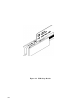
Figure 1-1.
SECTION 1. FEATURES AND SPECIFICATIONS USB KB SWIPE READER The USB (Universal Serial Bus) Keyboard Emulation Swipe Reader is a compact magnetic stripe card reader with a single read head that conforms to ISO standards. The Reader is compatible with any device with a USB interface. A card is read by sliding it, stripe down and facing the LED side, through the slot either forward or backward.
USB Keyboard Emulation Swipe Reader FEATURES Major features of the Swipe Reader are as follows: • • • • • • • • • • • • • Powered through the USB – no external power supply required Hardware Compatible with PC or any computer or terminal with a USB interface Bidirectional card reading Reads encoded data that meets ANSI/ISO/AAMVA/JIS Type 2 standards and others such as ISO track 1 format on track 2 or 3 Reads up to three tracks of card data LED for status Compatible with USB specification Revision 1.
Section 1. Features and Specifications HARDWARE CONFIGURATIONS The hardware configurations for the USB KB Swipe Reader are as follows: Part Number 21040107 21040108 21040109 21040110 21040122 21040123 Tracks TK 1,2,3 TK 1,2,3 TK 1,2 TK 1,2 TK 1,2 TK 1 (no SS/ES) Color Pearl White Black Pearl White Black Black Black Cable 6’ USB-A 6’ USB-A 6’ USB-A 6’ USB-A 5.
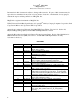
USB Keyboard Emulation Swipe Reader SPECIFICATIONS Table 1-1 lists the specifications for the USB Swipe Reader. Figure 1-2 shows the dimensions for the standard product. Table 1-1. Specifications Reference Standards Power Input Recording Method Message Format Card Speed Current Normal Mode Suspend Mode ISO 7810, ISO 7811, AAMVA and JIS X 6302* 5V From USB bus Two-frequency coherent phase (F2F) ASCII 3 to 60 ips (7.62 – 152.
Section 1. Features and Specifications Figure 1-2.
USB Keyboard Emulation Swipe Reader 6
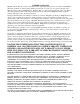
SECTION 2. INSTALLATION This section describes the cable connection, the Windows Plug and Play Setup, and the physical mounting of the unit. USB CONNECTION Connect the USB cable to a USB port on the host. The Reader, LED Indicator, and pin numbers for the 4-pin connector are shown in Figure 2-1. Figure 2-1. Reader Cable and Connector Pin numbers and signal descriptions for the cable shown in the illustration are listed in Table 2-1. Table 2-1.
USB Keyboard Emulation Swipe Reader WINDOWS PLUG AND PLAY SETUP On hosts with the Windows operating system, the first time the device is plugged into a specific USB port, Windows will pop up a dialog box, which will guide you through the process of installing a device driver for the device. After this process is completed once, Windows will no longer request this process as long as the device is plugged into the same USB port.
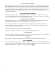
Section 2. Installation Figure 2-2. Mounting Hole Dimensions for Surface 2. Ensure the Reader is positioned on a flat, accessible surface with at least 4 inches clearance on either end for room to swipe a card. Orient the Reader so the side with the LED is facing the direction of intended use. If fastening tape is to be used, clean the area that the Reader will be mounted on with isopropyl alcohol. Remove the adhesive protective cover on the fastening tape, and position the Reader and push down firmly.
USB Keyboard Emulation Swipe Reader 10
SECTION 3. OPERATION This section describes the LED Indicator and Card Read. LED INDICATOR The LED indicator will be either off, red, or green. When the device is not powered, the LED will be off. When the device is first plugged in, the LED will be red. As soon as the device is plugged in, the host will try to enumerate the device. Once the device is enumerated the LED will turn green indicating that the device is ready for use.
USB Keyboard Emulation Swipe Reader 12
SECTION 4. USB COMMUNICATIONS This device conforms to the USB specification revision 1.1. This device also conforms with the Human Interface Device (HID) class specification version 1.1. The device communicates to the host as a HID keyboard device. The latest versions of the Windows operating systems come with a standard Windows USB HID keyboard driver. This is a full speed USB device. This device has a number of programmable configuration properties. These properties are stored in non-volatile memory.
USB Keyboard Emulation Swipe Reader Because of potential “data interleave” issues associated with the USB Keyboard interface, MagTek recommends that the USB Keyboard Emulation MSR product should only be used by customers who have previously used MagTek’s Keyboard Wedge MSR, or who are interfacing with an existing PC software application which gathers card data from the keyboard port.
Section 4.
USB Keyboard Emulation Swipe Reader HID USAGES HID devices send data in reports. Elements of data in a report are identified by unique identifiers called usages. The structure of the device’s reports and the device’s capabilities are reported to the host in a report descriptor. The host usually gets the report descriptor only once, right after the device is plugged in. The report descriptor usages identify the devices capabilities and report structures.
Section 4.
USB Keyboard Emulation Swipe Reader COMMAND NUMBER This one-byte field contains the value of the requested command number. The following table lists all the existing commands.
Section 4. USB Communications GET AND SET PROPERTY COMMANDS The Get Property command gets a property from the device. The Get Property command number is 0x00. The Set Property command sets a property in the device. The Set Property command number is 0x01.
USB Keyboard Emulation Swipe Reader 0E 0F POST_TK_CHAR ASCII_TO_KEYPRESS_CONVERSION_TYPE 10 11 12 13 14 16 16 INTERFACE_TYPE ACTIVE_KEYMAP PRE_CARD_STRING POST_CARD_STRING SS_TK1_ISO_ABA SS_TK2_ISO_ABA ES 17 18 ES_TK1 ES_TK2 19 1A 1B 1C 1D 1E ES_TK3 DECODE_ENABLE SS_JIS_TYPE_2 ES_JIS_TYPE_2 PAN_NAME_DATE_ENABLE POST_TK_CHAR_ENABLE Post track char Type of conversion performed when converting ASCII data to key strokes Type of USB interface Selects which key map to uses Pre card string Post card string
Section 4. USB Communications SERIAL_NUM PROPERTY Property ID: Property Type: Length: Get Property: Set Property: Default Value: Description: 0x01 String 0 – 15 bytes Yes Yes The default value is no string with a length of zero. The value is an ASCII string that represents the device’s serial number. This string can be 0 – 15 bytes long. The value of this property, if any, will be sent to the host when the host requests the USB string descriptor.
USB Keyboard Emulation Swipe Reader POLLING_INTERVAL PROPERTY Property ID: Property Type: Length: Get Property: Set Property: Default Value: Description: 0x02 Byte 1 byte Yes Yes 1 The value is a byte that represents the devices polling interval for the Interrupt In Endpoint. The value can be set in the range of 1 – 255 and has units of milliseconds. The polling interval tells the host how often to poll the device for card data packets.
Section 4.
USB Keyboard Emulation Swipe Reader TRACK_DATA_SEND_FLAGS PROPERTY Property ID: Property Type: Length: Get Property: Set Property: Default Value: Description: ICL 0x04 Byte 1 byte Yes Yes 0x63 This property is defined as follows: SS ES LRC 0 LC Er Er ICL 0 – Changing the state of the caps lock key will not affect the case of the data 1 – Changing the state of the caps lock key will affect the case of the data SS 0 – Don’t send Start Sentinel for each track 1 – Send Start Sentinel for each track
Section 4. USB Communications TERMINATION_CHAR PROPERTY Property ID: Property Type: Length: Get Property: Set Property: Default Value: Description: mod 0x05 Byte 1 byte Yes Yes 0x0D (carriage return) This property is defined as follows: c c c c c c mod 0 – Send c after card data 1 – Send c after each track c 1-127 – 7 bit ASCII char code 0 – send nothing c This property is stored in non-volatile memory, so it will persist when the unit is power cycled.
USB Keyboard Emulation Swipe Reader SS_TK3_ISO_ABA PROPERTY Property ID: Property Type: Length: Get Property: Set Property: Default Value: Description: 0x08 Byte 1 byte Yes Yes 0x2B ‘+’ This character is sent as the track 3 start sentinel for cards that have track 3 encoded in ISO/ABA format. If the value is 0 no character is sent. If the value is in the range 1 – 127 then the equivalent ASCII character will be sent.
Section 4. USB Communications PRE_CARD_CHAR PROPERTY Property ID: Property Type: Length: Get Property: Set Property: Default Value: Description: 0x0B Byte 1 byte Yes Yes 0 This character is sent prior to all other card data. If the value is 0 no character is sent. If the value is in the range 1 – 127 then the equivalent ASCII character will be sent. This property is stored in non-volatile memory, so it will persist when the unit is power cycled.
USB Keyboard Emulation Swipe Reader This property is stored in non-volatile memory, so it will persist when the unit is power cycled. When this property is changed, the unit must be reset (see Command Number 2) or power cycled to have these changes take effect. POST_TK_CHAR PROPERTY Property ID: Property Type: Length: Get Property: Set Property: Default Value: Description: 0x0E Byte 1 byte Yes Yes 0 This character is sent after the data for each track. If the value is 0 no character is sent.
Section 4. USB Communications ASCII code mode is slightly slower than keymap mode because more key presses need to be transmitted. Some applications are not compatible with ALT ASCII code mode. This property is stored in non-volatile memory, so it will persist when the unit is power cycled. When this property is changed, the unit must be reset (see Command Number 2) or power cycled to have these changes take effect.
USB Keyboard Emulation Swipe Reader Example Set Interface Type property to HID Request (Hex): Cmd Num 01 Data Len 02 Prp ID 10 Prp Value 00 Example Set Interface Type property Response (Hex): Result Code 00 Data Len 00 Data Example Get Interface Type property Request (Hex): Cmd Num 00 Data Len 01 Prp ID 10 Example Get Interface Type property Response (Hex): Result Code 00 Data Len 01 Prp Value 00 ACTIVE_KEYMAP PROPERTY Property ID: Property Type: Length: Get Property: Set Property: Default Val
Section 4. USB Communications Example Set Active Keymap property Response (Hex): Result Code 00 Data Len 00 Data Example Get Active Keymap property Request (Hex): Cmd Num 00 Data Len 01 Prp ID 11 Example Get Active Keymap property Response (Hex): Result Code 00 Data Len 01 Prp Value 00 PRE_CARD_STRING PROPERTY Property ID: Property Type: Length: Get Property: Set Property: Default Value: Description: 0x12 String 0 – 7 bytes Yes Yes The default value is no string with a length of zero.
USB Keyboard Emulation Swipe Reader POST_CARD_STRING PROPERTY Property ID: Property Type: Length: Get Property: Set Property: Default Value: Description: 0x13 String 0 – 7 bytes Yes Yes The default value is no string with a length of zero. The value is an ASCII string that represents the device’s post card string. This string can be 0 – 7 bytes long. This string is sent after all other card data. This property is stored in non-volatile memory, so it will persist when the unit is power cycled.
Section 4. USB Communications SS_TK2_ISO_ABA PROPERTY Property ID: Property Type: Length: Get Property: Set Property: Default Value: Description: 0x15 Byte 1 byte Yes Yes 0x3B ‘;’ This character is sent as the track 2 start sentinel for cards that have track 2 encoded in ISO/ABA format. If the value is 0 no character is sent. If the value is in the range 1 – 127 then the equivalent ASCII character will be sent.
USB Keyboard Emulation Swipe Reader This property is stored in non-volatile memory, so it will persist when the unit is power cycled. When this property is changed, the unit must be reset (see Command Number 2) or power cycled to have these changes take effect. Note This property only applies to swipe readers, not the SureSwipe readers.
Section 4. USB Communications Note This property only applies to swipe readers, not the SureSwipe readers.
USB Keyboard Emulation Swipe Reader SS_JIS_TYPE_2 PROPERTY Property ID: Property Type: Length: Get Property: Set Property: Default Value: Description: 0x1B Byte 1 byte Yes Yes 0x7F ‘DEL’ This character is sent as the start sentinel for cards that are encoded in the JIS type 2 format. If the value is in the range 0 – 127 then the equivalent ASCII character will be sent. This property is stored in non-volatile memory, so it will persist when the unit is power cycled.
Section 4. USB Communications Description: When this property is set to 0, the reader data transmission will use the standard mode of sending track information as described in SECTION 4.
USB Keyboard Emulation Swipe Reader POST_TK_CHAR_ENABLE PROPERTY Property ID: Property Type: Length: Get Property: Set Property: Default Value: Description: 0x1E Byte 1 byte Yes Yes 0x07 This property is used to enable or disable the post track character for each track individually. The post track character is set separately with the post track character property. To enable the post track character for a given track set its corresponding bit position to one. To disable it, set it to zero.
Section 4. USB Communications Example Response (Hex): Result Code 00 Data Len 00 Data GET_KEYMAP_ITEM COMMAND Command number: Description: 0x03 This command is used to get a key map item from the active key map. The active key map is determined by the active key map property. Data from a magnetic stripe card is a sequence of ASCII characters. These ASCII characters are mapped to key strokes and these key strokes are sent to the host to represent the ASCII character.
USB Keyboard Emulation Swipe Reader Response Data: Offset 0 Field Name Key Usage ID 1 Key Modifier Byte Description The value of the USB key usage ID that is mapped to the given ASCII value. For example, for the United States keyboard map, usage ID 56 (0x38) (keyboard / and ?) is mapped to ASCII character ‘?’. The value of the USB key modifier byte that is mapped to the given ASCII value.
Section 4. USB Communications values. The ALT ASCII code is a key press combination consisting of the decimal value of the ASCII character combined with the ALT key modifier. For example, to transmit the ASCII character ‘?’ (063 decimal), keypad ‘0’ is sent combined with left ALT key modifier, next keypad ‘6’ is sent combined with the left ALT key modifier, last keypad ‘3’ is sent combined with the left ALT key modifier.
USB Keyboard Emulation Swipe Reader SAVE_CUSTOM_KEYMAP COMMAND Command number: Description: 0x05 This command is used to save the active key map as the custom key map in non volatile memory. The active key map is determined by the active key map property. Once a key map item is modified, the changes take affect immediately. However, the changes will be lost if the device is reset or power cycled. To make the changes permanent, the save custom key map command must be issued.
SECTION 5. DEMO PROGRAM The purpose of this demo program is not to demonstrate card reading with this Keyboard Emulation device. Use a text editor application such as Windows Notepad to demonstrate card reading for this keyboard emulation device. Any application that allows user input from a keyboard should be sufficient to demonstrate card reading for this device.
USB Keyboard Emulation Swipe Reader • • • • Enter a command in the Message edit box. All data entered should be in hexadecimal bytes with a space between each byte. Enter the command number followed by the command data if there is any. The application will automatically calculate and send the command data length for you. For example, to send the GET_PROPERTY command for property SOFTWARE_ID enter 00 00. Press Enter or click on Send message to send the command and receive the result.
APPENDIX A. USAGE ID DEFINITIONS This appendix is from the following document found on www.usb.org: Universal Serial Bus HID Usage Tables, Version 1.12 and specifically for this manual, Section 10, Keyboard/Keypad Page (0x07). KEYBOARD/KEYPAD PAGE (0X07) This section is the Usage Page for key codes to be used in implementing a USB keyboard. A Boot Keyboard (84-, 101- or 104-key) should at a minimum support all associated usage codes as indicated in the “Boot” column below.
20 14 Keyboard q and Q 21 15 Keyboard r and R 4 Boot 27 √ √ √ 4/101/104 20 √ √ √ 4/101/104 22 16 Keyboard s and S 32 √ √ √ 4/101/104 23 17 Keyboard t and T 21 √ √ √ 4/101/104 24 18 Keyboard u and U 23 √ √ √ 4/101/104 25 19 Keyboard v and V 49 √ √ √ 4/101/104 4 1A Keyboard w and W 18 √ √ √ 4/101/104 27 1B Keyboard x and X 4 47 √ √ √ 4/101/104 28 1C Keyboard y and Y 4 22 √ √ √ 4/101/104 4 26 29 30 4 1D Keyboard z and Z 46 √ √
Ref: Typical AT-101 Position PC-AT Mac UNIX Universal Serial Bus HID Tables Boot Keyboard F3 114 √ √ √ 4/101/104 3D Keyboard F4 115 √ √ √ 4/101/104 62 3E Keyboard F5 116 √ √ √ 4/101/104 63 3F Keyboard F6 117 √ √ √ 4/101/104 64 40 Keyboard F7 118 √ √ √ 4/101/104 65 41 Keyboard F8 119 √ √ √ 4/101/104 66 42 Keyboard F9 120 √ √ √ 4/101/104 67 43 Keyboard F10 121 √ √ √ 4/101/104 68 44 Keyboard F11 122 √ √ √ 101/104 69 45 Keyboard F12 U
99 63 100 101 102 65 66 Keypad .
139 8B Keyboard International5 19 140 8C Keyboard International6 20 141 8D Keyboard International7 21 142 8E Keyboard International8 22 143 8F Keyboard International9 22 144 90 Keyboard Lang1 25 145 91 Keyboard Lang2 26 146 92 Keyboard Lang3 30 147 93 Keyboard Lang4 148 94 Keyboard Lang5 32 149 95 Keyboard Lang6 8 150 96 Keyboard Lang7 8 151 97 Keyboard Lang8 8 152 98 Keyboard Lang9 8 153 99 Keyboard Alternate Erase 154 9A Keyboard Sys/Req Attentio
188 BC Keypad A 189 BD Keypad B 190 BE Keypad C 191 BF Keypad D 192 C0 Keypad E 193 C1 Keypad F 194 C2 Keypad XOR 195 C3 Keypad ^ 196 C4 Keypad % 197 C5 Keypad < 198 C6 Keypad > 199 C7 Keypad & 200 C8 Keypad && 201 C9 Keypad | 202 CA Keypad || 203 CB Keypad : 204 CC Keypad # 205 CD Keypad Space 206 CE Keypad @ 207 CF Keypad ! 208 D0 Keypad Memory Store 209 D1 Keypad Memory Recall 210 D2 Keypad Memory Clear 211 D3 Keypad Memory Add 212
229 E5 Keyboard RightShift 230 E6 Keyboard RightAlt 231 E7 232 – 65535 E8-FFFF Usage Name 10;24 Keyboard Right GUI Ref: Typical AT-101 Position UNIX Usage ID (Hex) Mac Usage ID (Dec) PC-AT Universal Serial Bus HID Tables 57 √ √ √ 62 √ √ √ 128 √ √ √ Boot Reserved Footnotes 1. Usage of keys is not modified by the state of the Control, Alt, Shift or Num Lock keys. That is, a key does not send extra codes to compensate for the state of any Control, Alt, Shift or Num Lock keys.
USB Keyboard Emulation Swipe Reader 52
APPENDIX B. MODIFIER BYTE DEFINITIONS This appendix is from the following document found on www.usb.org: Device Class Definition for Human Interface Devices (HID) Version 1.11, and specifically for this manual, Section 8.3 Report Format for Array Items. The modifier byte is defined as follows: Table B-1.
USB Keyboard Emulation Swipe Reader 54