ExpressCard 2000 Instant Issuance Card Personalization System Hardware Service Manual June 2014 Manual Part Number: 99875607-4.01 REGISTERED TO ISO 9001:2008 MagTek I 1710 Apollo Court I Seal Beach, CA 90740 I Phone: (562) 546-6400 I Technical Support: (888) 624-8350 www.magtek.
Copyright © 2006 - 2014 MagTek, Inc. Printed in the United States of America Information in this publication is subject to change without notice and may contain technical inaccuracies or graphical discrepancies. Changes or improvements made to this product will be updated in the next publication release. No part of this document may be reproduced or transmitted in any form or by any means, electronic or mechanical, for any purpose, without the express written permission of MagTek, Inc.
SAFETY This product has been evaluated by multiple safety certification agencies, including Underwriters Laboratories (UL) and the United States Federal Communications Commission (FCC Class A and Class B), and is designed to protect both the user and the device. This document is written specifically to work in conjunction with these safety and integrity features to protect the user and the device.
0 - Table of Contents Table of Contents Table of Contents ............................................................................................................................... 4 1 2 3 Required Tools, Materials, and Documents ........................................................................... 7 1.1 Required Tools ..................................................................................................................... 7 1.2 Suggested Tools .................................
0 - Table of Contents 4 5 6 Removal and Re-installation .................................................................................................. 43 4.1 How to Prepare the Device for Removing / Re-installing Modules........................... 43 4.2 How to Remove / Re-install the Top Access Door ....................................................... 44 4.3 How to Remove / Re-install the Side Access Doors .................................................... 48 4.
1 - Table of Contents Appendix C Key Loading ..........................................................................................................
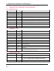
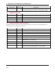
1 - Required Tools, Materials, and Documents 1 Required Tools, Materials, and Documents 1.1 Required Tools Part Number Quantity Description 33011008 1 ea. ASM TOOL KIT,FIELD SERVICE,EC2000 67800019 or equiv. 1 ea. Small USB keyboard with touchpad mouse N/A 1 ea. Small diagonal side cutters N/A 1 ea. X-Acto knife (if removing embosser characters) N/A 1 ea. Micrometer or digital calipers (if calibrating embosser) N/A 1 ea. ESD grounding wrist strap N/A 1 ea.
1 - Required Tools, Materials, and Documents Part Number 97200121 or equiv. 1.4 Quantity ~10ml Description MSP ADHESIVE,RTV SILICONE,90ML,CLEAR If removing image printer, touchscreen, embedded PC, or MSR Suggested Materials Part Number Quantity Description 33011009 1 ea. ASM KIT,STARTER,SPARE,FIELD SERVICE,EC2000 93400047 1 ea. PRI RIBBON, COLOR YMCKOK EV (R3314) 33070896 1 ea. ASM RIBBON ASSY,TIP FOIL,SILVER 33070621 1 ea. AAY ASSY,INDENT CARTRIDGE 1.
2 - Introduction 2 Introduction This document provides detailed information about maintaining the ExpressCard 2000 (EC2000). It is part of the ExpressCard 2000 Service Library, which includes: 99875600 ExpressCard 2000 User Installation and Operation Manual 99875607 ExpressCard 2000 Hardware Service Manual 99875609 ExpressCard 2000 Parts Catalog Documents in the service library reference each other frequently and are designed to be used together. 2.
2 - Introduction Do not place an ESD-sensitive part on the device or on a metal table; put it in an ESD bag or on an ESD mat. Use extra caution when working under climate conditions that increase the potential for ESD, such as cold weather or low humidity. 2.4 Introduction to EC2000 Components For an introduction to identifying the components of the EC2000, see 99875600 EC2000 User Installation and Operation Manual.
2 - Introduction 2.6 About Installation & Operation For detailed instructions about planning, installation, operation, and basic maintenance, see 99875600 EC2000 User Installation and Operation Manual. 2.7 How to Open the Top Access Door For instructions to open the top access door, see 99875600 EC2000 User Installation and Operation Manual. Some procedures require removing the top access door completely. For removal instructions, see section 4.2 How to Remove / Re-install the Top Access Door. 2.
2 - Introduction 2.9 How to Use Maintenance Functions On the Touchscreen This section explains how to use the maintenance functions on the EC2000’s touchscreen. Most of the functions let you isolate the various subsystems during troubleshooting to determine the failure point, and to verify repairs have corrected the problem. To visually inspect the device while it is running, open the top access door and block the sensor mounted to the rear left of the top access door track.
2 - Introduction Press This Button Verify This Happens 2 To Hopper Hopper transport moves to (or stays at) hopper 1 1 To Hopper Hopper transport moves to (or stays at) hopper 1 Bot Cartridge Unload , Indenter Move Rear (black) indent cartridge moves out of embosser toward rear of device Bot Cartridge Load , Indenter Move Rear (black) indent cartridge moves back into embosser Bot Cartridge Home , Indenter Move Rear (black) indent cartridge moves back into (or stays in) embosser Bot Cart to Indent
2 - Introduction Press This Button Verify This Happens Clamp Card X carriage clamps card at printer exit Embosser Home Embosser wheel moves to first character on wheel (look for empty tines next to the tine that is currently between the hammers) Embosser hammers open completely (not squeezing embosser tines) Wheel Home Embosser wheel moves to first character on wheel (look for empty tines next to the tine that is currently between the hammers) XY To Embosser XY Transport moves card out of printer a
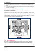
2 - Introduction 2.9.2 How to Use the Sensor Utility Page To check the real-time status of all EC2000 sensors, use the touchscreen to navigate to Menu > Settings > Sensors to open the Sensor Utility page. In normal operation with the top access door closed, with all card stock hoppers inserted, and with the device just powered up and ready to process cards, the Sensor Utility page should match Figure 2-3. Figure 2-3 - Sensor Utility Page To test a sensor, block or unblock it and verify its status changes.
2 - Introduction Sensor Name Function Card Edge Blocked EITHER when the embosser daisy wheel is turned such that one of the tines blocks the sensor, OR when a card enters the area between the embosser wheels. Wheel Home Blocked when the small fin on top of the embosser daisy wheel points toward the front of the device. Top Case Blocked when the top access door is closed.
2 - Introduction Figure 2-4 - All EC2000 Sensors Shown In Red (FRONT VIEW) ExpressCard 2000| Instant Issuance Card Personalization System | Hardware Service Manual Page 17
2 - Introduction 2.9.3 How to Use the Embosser Utility Page 2.9.3.1 About the Embosser Utility Page To manually move the embosser daisy wheel or hammer cam motors, or to adjust the depth of individual embossed characters, use the touchscreen to navigate to Menu > Settings > Service > Embosser , then enter service passwords 4567890 and 0987654 to open the Embosser Utility page.
2 - Introduction 4) Re-home the daisy wheel by pressing either the Counter Clockwise Home or Clockwise Home button. In normal operation, the daisy wheel homes counter-clockwise. 5) Press the All Motors Stop button to make sure the daisy wheel motor is not energized / holding still. 6) Press the Status button to return to the Status page. 2.9.3.
2 - Introduction Figure 2-6 - Emboss Settings Page To adjust a single character’s pressing force or hold time, do the following: 1) Open the Emboss Settings page: Navigate to Menu > Settings > Service > Embosser and enter service passwords 4567890 and 0987654 to open the Embosser Utility page, then press the Settings button below Set Emboss Hold Time & Height . 2) Press the Get button to refresh the settings shown in the Current Settings in Device list box.
2 - Introduction 2.9.4 How to Use the Character Mapping Page The Character Mapping page provides support for changing the configuration of characters on the EC2000 embosser’s daisy wheel, and will most commonly be used in conjunction with the steps in section 4.10 How to Remove / Re-install Embosser Fonts and in section 4.11 How to Remove / Reinstall the Embosser. Functions include adding new fonts, moving an existing character to a different tine, and removing a character from a tine.
2 - Introduction 1) Verify the EC2000 software supports the character(s) you are going to install. 2) Look at the numbers stamped on each daisy wheel tine to find the number of the tine where you will install the new character. 3) Install the character on the tine.
3 - Preventive Maintenance 3 Preventive Maintenance The EC2000 requires regular preventive maintenance to maintain image quality and reliability. Follow the steps in each section below to perform preventive maintenance. Before starting, ask the EC2000 user or customer if they have had any specific problems with the device. If you need to troubleshoot a specific problem, address that before performing preventive maintenance. See section 6 Diagnosis for assistance troubleshooting reported issues.
3 - Preventive Maintenance ExpressCard 2000| Instant Issuance Card Personalization System | Hardware Service Manual Page 24
3 - Preventive Maintenance 3.1 Prepare the Device for Preventive Maintenance To prepare the device for service, follow these steps: 1) Offer the customer the opportunity to remove any proprietary or security-sensitive consumables from the device, including card stock, image printer ribbons, indent cartridges, and tipper foils. Some consumables contain negative imprints of cardholder data and must be handled securely. 2) Make sure the device is powered up and connected to the network.
3 - Preventive Maintenance Figure 3-1 - Cleaning the Hopper Transport Rollers (TOP VIEW FROM FRONT) b) Feed the card partly into the left side of the exit transport and press the Exit Eject button. Hold the card there until the rollers stop moving. Figure 3-2 - Cleaning the Left Side of the Exit Transport (TOP VIEW FROM FRONT) c) Feed the card partly into the right side of the exit transport and press the Exit Reject button.
3 - Preventive Maintenance Figure 3-3 - Cleaning the Right Side of the Exit Transport (TOP VIEW FROM FRONT) d) Feed the card partly under the exit ramp rollers and press the Exit Eject button. Hold the card there until the rollers stop moving. Figure 3-4 - Cleaning the Exit Ramp Rollers (TOP VIEW FROM FRONT) 5) Press the Status button to return to the Status page. 6) Re-install the tipper foil spool assembly with the original tipper foil roll, or obtain and install a new one from the customer.
3 - Preventive Maintenance 3.4 Update the Software If MagTek Support Services has supplied .CAB files to apply EC2000 software patches, follow these steps to install them: 1) Use the Ethernet cable to connect the service laptop to the EC2000. If necessary, you may instead use the customer’s instant issuance workstation, provided it has Microsoft Internet Explorer and a USB port with security settings that allow you to read from the USB thumb drive.
3 - Preventive Maintenance 3.5 Update the Firmware Follow the steps in this section to determine whether the EC2000 firmware needs to be updated, and to update it if necessary. 3.5.1 Check Firmware Revision Numbers To check whether the EC2000 has the latest main logic board (MLB) and image printer firmware installed, follow these steps: 1) Install any software updates MagTek Support Services has provided, using the instructions in section 3.4 Update the Software.
3 - Preventive Maintenance 3.5.2 Update the Main Logic Board (Controller) Firmware To update the controller (main logic board / MLB) firmware, follow these steps: 1) From the Firmware Download page, select the Controller radio button. 2) In the list of .hex files, select the file that corresponds to the new revision. 3) Press the Download button to download the .hex file to the controller. The system will report “Loading the firmware. Please wait….
3 - Preventive Maintenance 4) Wait about 5 minutes for the firmware to finish downloading. Do not power off the device. 5) After the firmware update is complete, the device will make sounds as the MLB resets. Wait until the sounds stop and the touchscreen reports “Finished loading the firmware.
3 - Preventive Maintenance 3.5.3 Update the Printer Firmware To update the printer firmware, follow the steps from section 3.5.2, but select the Printer radio button and select the .hex file appropriate to the revision of the image printer firmware you want to install, before pressing the Download button.
3 - Preventive Maintenance 3.6 Service the Hopper Module Follow these steps to service the hopper transport: 1) Use the MCP Commands page (see section 2.9 How to Use Maintenance Functions On the Touchscreen) to move the hopper transport from the front to the rear of the device to verify the movement is smooth and there is no belt slippage. 2) Only if the hopper transport rods are dirty, wipe off the dirt with a soft, lint-free cloth. 3) Check the hopper transport drive belt for signs of damage.
3 - Preventive Maintenance 3.7 Service the XY Transport Module Do not lubricate the EC2000’s gears or bearings. They are made of self-lubricating powder metal, and lubricants can damage their surfaces. Follow these steps to lubricate the one shaft that requires lubrication. Do not use Tri-Flow lubricant on any shaft other than the one shown below. 1) If there is dirt, dust, or debris on the XY transport rods, wipe it off using a soft, lint-free cloth. 2) Use the MCP Commands page (see section 2.9.
3 - Preventive Maintenance Figure 3-6 - Run a Thin Bead of Tri-Flow Along the Top of the Shaft (TOP LEFT VIEW) 7) Use the drive belt to move the XY transport to the front of the device, then to the rear again to spread the Tri-Flow along the length of the shaft (see section 2.8 How to Safely Move Transports By Hand). 8) If you have applied too much Tri-Flow to the shaft, some may drip off the shaft. If this happens, dab off the excess with a clean, lint free cloth.
3 - Preventive Maintenance 3.8 Service the Exit Transport Module No additional service is necessary for the Exit Transport, other than the roller cleaning described in section 3.3 Clean All Transport Rollers. 3.9 Cool the Tipper Heater / Power Down the Device 1) Navigate to Menu > Settings > Tipper to open the Tipper page. 2) Press the Set Heater OFF button to turn off the tipper heater. 3) Note the value under Current Tipper Temp.
3 - Preventive Maintenance 3.10 Clean Inside the Device Caution: Do not use alcohol wipes, liquids, or chemicals on the touchscreen. Clean the device in phases to avoid blowing dirt, dust, or debris into sensitive components: 1) Remove all remaining consumables from the device (stock cards, image printer ribbon, indent cartridge[s], tipper foil, etc.) and set them aside in a secure location or give them to the customer for temporary storage or secure disposal.
3 - Preventive Maintenance 3.11 Service the Image Printer Module Follow these steps to service the image printer: 1) Make sure the interior of the EC2000 is clean (see section 3.10 Clean Inside the Device). Performing image printer maintenance with dirt or debris inside the cover may damage the printer. 2) Open the image printer and clean its interior if necessary.
3 - Preventive Maintenance 3.12 Service the Embosser Module 3.12.1 About Servicing the Embosser Module The embosser module presses characters into card stock by squeezing the card between a raised metal letter, called a punch, and an indented letter of the same shape, called a die, installed on the embosser’s top and bottom daisy wheels. For indented characters, the die is replaced with a flat metal plate so the card stock is only altered on the character side.
3 - Preventive Maintenance 3.12.2 How to Service the Embosser Module Service the embosser by following these steps. If you discover any issues you can not resolve, contact MagTek Support Services to procure a replacement embosser module. 1) Use compressed air to clean the embosser bridge (the metal block between the daisy wheels that supports the indent cartridge ribbon). 2) Inspect the top and bottom embosser daisy wheels for missing or worn characters and replace them if possible (see section 4.
3 - Preventive Maintenance Figure 3-8 - Using Inspection Mirror to Check Tine / Hammer Alignment (TOP VIEW FROM FRONT) Figure 3-9 - Bad Embosser Wheel Alignment (Figure 3-8 MAGNIFIED) 6) If any cones are broken or bent, replace the characters in the same location if possible.
3 - Preventive Maintenance 3.13 Service the Electronics Visually inspect all wires and cables, checking for insulation breakage or wear on moving cables. 3.14 Service the Cover After completing all other service, service the cover as follows: 1) Inspect the cover for damage. 2) Clean the black and gray portions of the outside of the cover with alcohol wipes. 3) Clean fingerprints off the touchscreen with a soft, clean, dry cloth. 3.
4 - Removal and Re-installation 4 Removal and Re-installation This section describes how to remove and re-install the major assemblies within the EC2000. To avoid personal injury or damage to the device, be sure to follow ESD procedures (see section 2.3 How to Handle ESD-Sensitive Parts) and use standard safety practices. 4.
4 - Removal and Re-installation 4.2 How to Remove / Re-install the Top Access Door Approximate time to remove: 5 minutes plus any sub-procedures Approximate time to re-install: 5 minutes plus any sub-procedures The top access door is the large lockable door in the top of the cover that secures the user-serviceable areas inside the device, while allowing users to access and replace consumable items like image printer ribbons and card stock.
4 - Removal and Re-installation 3) Using both hands, gently pull the top cover to the right, then slightly upward to free it from its left track as shown in Figure 4-2. Figure 4-2 - Pulling the Left Side of the Top Access Door Out of Its Track (FRONT VIEW) 4) Repeat the process, pulling it to the left and slightly upward, to free it from its right track. 5) Lean the top access door out toward the rear of the device as shown.
4 - Removal and Re-installation Figure 4-3 - Top Access Door Leaning Up and Back (FRONT VIEW) 6) Move the hopper transport toward the front of the device, around hopper 6 (see section 2.8 How to Safely Move Transports By Hand). 7) Remove card stock hoppers 1 and 2. 8) Locate the screw and washer that fasten the cover to the metal plate on the rear of the base. The fastener can be found in the rear upper right of the device behind hopper 1, as shown in Figure 4-4.
4 - Removal and Re-installation 12) Remove the bushings from the top cover’s two hinges (one on each side) and set them aside with the cover and the two screws and washers. Figure 4-5 - Top Access Door Hinge Bushings (FRONT LEFT VIEW) To re-install the top access door, reverse the steps for removing it. Be careful not to lose the door’s bushings, which are not secured to the cover or to the top access door’s hinges.
4 - Removal and Re-installation 4.
4 - Removal and Re-installation 6) Being careful not to pinch any cables or wires between the screwdriver and the screw, use the long No. 2 Philips screwdriver to unscrew the two thumb screws. 7) Lower the side access door to free its bottom tabs from the cover, remove it, and set it aside (see Figure 4-8).
4 - Removal and Re-installation 4.4 How to Remove / Re-install the Cover Approximate time to remove: 30 minutes plus any sub-procedures Approximate time to re-install: 45 minutes plus any sub-procedures The EC2000 has a cover which secures the device’s contents and provides mount points for the top access door and touchscreen, and incorporates the card output hopper and manual feed slot. Some service procedures require removing the device’s cover to give unobstructed access to certain components.
4 - Removal and Re-installation Figure 4-10 - Removing Card Stock Hoppers (LEFT VIEW) 5) Disconnect the BEZEL LED signal cable from the inside of the manual feed slot. Figure 4-11 - Bezel LED Signal Cable (REAR VIEW) 6) Disconnect the Exception Card Entry sensor cable in the front right corner of the device.
4 - Removal and Re-installation Figure 4-12 - Exception Card Entry Sensor Cable (REAR VIEW) 7) Disconnect the Door 1 sensor cable in the front right corner of the device. Figure 4-13 - Door 1 Sensor Cable (REAR VIEW) 8) Disconnect the touchscreen VGA video cable and the power cable from the rear of the touchscreen. If there is any silicone adhesive on the cables or their connections, remove it completely.
4 - Removal and Re-installation Figure 4-14 - Touchscreen VGA Cable and Power Cable (REAR VIEW) 9) If there are any cable ties anchoring the touchscreen cables to the cover, use the wire cutters or diagonal cutters to cut the cable ties, and replace them when re-installing the cover. Figure 4-15 - Touchscreen Power and VGA Cables (REAR VIEW) 10) Disconnect the Top Case Open sensor cable in the rear left corner of the device.
4 - Removal and Re-installation Figure 4-16 - Top Case Open Sensor Cable (RIGHT VIEW) 11) Disconnect the Door 2 Solenoid cable connected to the top access door latch on the left side of the device. Disengage the bottom part of the cable from the clip on the wall of the cover. Figure 4-17 - Door 2 Solenoid Cable (RIGHT VIEW) 13) Use the No. 2 Philips screwdriver to remove the fastener that secures the cover to the metal plate on the rear face of the base.
4 - Removal and Re-installation Figure 4-18 - Removing the Right Side Cover Screw Near Top Access Door Hinge (FRONT LEFT VIEW) 14) Use the No. 2 Philips screwdriver to remove the screw and washer in the rear upper left of the device, opposite the fastener you have already removed (see Figure 4-20).
4 - Removal and Re-installation Figure 4-20 - One of Eight Screws On Sides of Cover (TOP VIEW FROM FRONT) Figure 4-21 - Plastic Fastener Plates (LEFT VIEW) 14) Locate the two screws that secure the front of the cover next to the tipper.
4 - Removal and Re-installation Figure 4-22 - Cover Screws Next to Tipper (REAR VIEW) 15) Use the No. 2 Philips screwdriver to remove the screws and set them aside. 16) Pull the silver portion of the cover forward slightly to release it from the device. 17) Carefully remove the cover by pulling it forward a few inches with both hands, making sure there are no cables tangled with it, then pull it toward the ceiling and set it aside.
4 - Removal and Re-installation To re-install the cover, follow these steps: Note: Re-installing the cover is an intricate, detailed procedure that can affect the security and functionality of the device. Perform each step carefully and methodically, and make sure everything is in place before proceeding to the next step. 1) Move any loose cables toward the center of the device so they will not be in the way of the cover.
4 - Removal and Re-installation 6) Apply silicone adhesive to secure the touchscreen power and video cables as shown in Figure 4-25. Figure 4-25 - Silicone Adhesive On Touchscreen Connectors (REAR VIEW) 7) Bring the cover back up to resting squarely on the base as shown in Figure 4-24. 8) Stand in front of the device and look straight down over the front. Locate the extension of the cover’s card output hopper that will meet up with the end of the exit ramp (see Figure 4-26).
4 - Removal and Re-installation Figure 4-27 - Fitting the Silver Portion of the Cover (FRONT VIEW) 10) “Bump” the front of the silver portion of the cover (just to the right of the card output hopper) with the palm of your hand to firmly seat the cover in place. 11) Make sure the silver portion of the cover is solidly seated in the slot in the base, and that the darker portion of the cover is properly seated above it. See Figure 4-28 for reference.
4 - Removal and Re-installation 13) Use your fingers to insert the two screws that fasten the cover to the front of the device (see Figure 4-22), then use the No. 1 Philips screwdriver to loosely screw them into place to constrain the cover from moving left to right. 14) Loosely screw in the two screws that fasten the cover to the rear plate (see Figure 4-18 and Figure 4-19) to constrain the cover from moving front to rear. 15) Fully insert the eight screws that fasten the cover to the base.
4 - Removal and Re-installation 21) If the EC2000 does not power up or function properly, contact MagTek Support Services for assistance (see Appendix A Technical Support).
4 - Removal and Re-installation 4.5 How to Remove / Re-install the Hopper Module Approximate time to remove: 30 minutes plus any sub-procedures Approximate time to re-install: 30 minutes plus any sub-procedures The hopper module holds the device’s card stock hoppers and carries blank card stock to the image printer from the hoppers or from the manual feed slot. It is mounted to the top deck plate of the device along the right side.
4 - Removal and Re-installation 4) Remove all the card stock hoppers and set them aside in a secure location, or give them to the customer for secure temporary storage. Figure 4-31 - Save Removal Location for Hopper Transport (TOP VIEW FROM FRONT) 5) Disconnect the two sensor cables from the rear right of the hopper deck (see Figure 4-32).
4 - Removal and Re-installation Figure 4-33 – Hopper Module Breakout Board (TOP VIEW FROM FRONT) 10) Trace the hopper module’s flex cable to where it plugs in to the hopper transport (see Figure 4-34). Figure 4-34 - Hopper Transport Flex Cable Connection (FRONT RIGHT VIEW) 11) Disconnect the flex cable from the hopper transport, and carefully pull it free from the small pad of double-sided foam tape just next to the plug (see Figure 4-35).
4 - Removal and Re-installation Figure 4-35 - Disconnecting the Hopper Transport Flex Cable 12) Use the 5/32 in. ball end Allen wrench to remove the four screws that secure the four corners of the hopper module to the top deck plate. Some screws require inserting the Allen wrench through openings in the hopper deck plate. See Figure 4-30 and Figure 4-36 for reference. Figure 4-36 –3 of 4 Hopper Module Screws (TOP RIGHT VIEW) 13) Locate the hopper transport belt.
4 - Removal and Re-installation Figure 4-37 - Hopper Transport Belt Tension Adjustment Screw (FRONT RIGHT VIEW) 15) Carefully slip the hopper transport belt off the gear of the motor mounted to the top deck plate, near the rear of the hopper module (see Figure 4-38). Figure 4-38 - Hopper Transport Belt and Drive Motor (FRONT RIGHT VIEW) 16) Use both hands to carefully lift the hopper module out of the device, making sure no cables are snagged on the hopper module or the device, and set it aside.
4 - Removal and Re-installation To re-install the hopper module, follow these steps: 1) Note that if any cables or cable ties are too difficult to reach during the following steps, you can remove the hopper deck (the steel plate on the top of the hopper module); use the 5/64” Allen wrench to remove the five screws that secure it to the hopper module, and set the screws and deck aside. 2) On the replacement hopper module, move the hopper transport to hopper 4 (see section 2.
4 - Removal and Re-installation 6) Move the hopper transport to the front of the device, just past hopper 7 and before it rotates to the manual feed slot (see Figure 4-31 and section 2.8 How to Safely Move Transports By Hand). 7) Stick ¼” of double-stick tape to the hopper transport flex cable just behind the plug. 8) Plug the flex cable into the hopper transport so it points toward the rear of the device, and stick the double-stick tape to the hopper transport’s motor as shown.
4 - Removal and Re-installation 11) Loop a cable tie through the anchor point on the top deck plate near the front of the device, tie the EXC HOME SENS cable to the other cables, and tighten and trim the cable tie (see Figure 4-41). Figure 4-41 - EXC HOME SENS Cable Routing (TOP LEFT VIEW) 12) Continue routing the EXC HOME SENS cable along the right side of the device and thread it under the right side of the HOPPER SHUTTLE board, then out the front as shown in Figure 4-42.
4 - Removal and Re-installation Figure 4-43 - Securing the EXC HOME SENS Cable (TOP VIEW FROM FRONT) 14) Use a miniature cable tie to fasten the EXC HOME SENS cable to the same bundle of cables, near the flex cable as shown. 15) Locate the HOME SENS cable that comes from the rear of the hopper module. Route it along the rear wall of the device to the left side of the hopper module, and below the shielding around the image printer as shown in Figure 4-44.
4 - Removal and Re-installation Figure 4-44 - Preferred Routing for HOME SENS Cable (TOP VIEW FROM FRONT RIGHT) Figure 4-45 – Optional Routing for Tighter HOME SENS Cable (TOP VIEW FROM FRONT RIGHT) 16) Continue routing the HOME SENS cable along the bundle of cables that runs below the left edge of the hopper module. Use cable ties to re-bundle the cables as shown in Figure 4-46.
4 - Removal and Re-installation Figure 4-46 - Routing the HOME SENS Cable (TOP FRONT VIEW) 17) Continue routing the HOME SENS cable under the clip just to the left of the HOPPER SHUTTLE circuit board as shown in Figure 4-47. Figure 4-47 - Routing the HOME SENS Cable (FRONT VIEW) 18) Plug the two sensor cables into the HOPPER SHUTTLE circuit board (see Figure 4-48). a) The HOME SENS cable from the rear of the hopper module plugs into the left connector, labeled HOME SENS.
4 - Removal and Re-installation Figure 4-48 - Sensor Cables Plugged In To HOPPER SHUTTLE Circuit Board (FRONT VIEW) 19) Plug the two sensor cables at the rear of the device into the two plugs on the circuit board at the top rear right of the hopper module. The cable labeled “…to J2…” goes to the REAR plug, and the cable labeled “…to J1…” goes to the FRONT plug. See Figure 4-49.
4 - Removal and Re-installation Figure 4-50 - Attaching Hopper Transport Drive Belt (FRONT RIGHT VIEW) 21) Use the 5/32” Allen wrench to insert and tighten the four screws that secure the hopper module to the top deck plate (see Figure 4-30 at the beginning of this section). 22) Use the 5/32” Allen wrench to tighten the belt tensioner screw on the front of the hopper module (see Figure 4-37) so the top and bottom of the drive belt are parallel with each other and the belt feels tight to your fingers.
4 - Removal and Re-installation 4.6 How to Remove / Re-install the Image Print Head For detailed instructions to replace the image print head, see 99875600 EC2000 User Installation and Operation Manual.
4 - Removal and Re-installation 4.7 How to Remove / Re-install the Image Printer Module Approximate time to remove: 15 minutes plus any sub-procedures Approximate time to re-install: 15 minutes plus any sub-procedures The image printer, located in the rear center of the device, takes blank card stock from the hopper transport, encodes any required data onto the card, produces images on both sides, and ejects the card out the other side to be retrieved by the XY transport.
4 - Removal and Re-installation 3) Disengage and lean back the top access door by following the steps in section 4.2 How to Remove / Re-install the Top Access Door up to the point where the top access door is leaning up and back behind the device (Figure 4-3). 4) Remove the image printer ribbon and set it aside in a secure location or give it to the customer for temporary storage or secure disposal. 5) Move the hopper transport away from the image printer, toward the front of the device (see section 2.
4 - Removal and Re-installation 8) Near the front left screw of the image printer, locate the cable labeled Y END SENSOR, shown in Figure 4-54, and disconnect it. Figure 4-54 - Image Printer Exit Sensor Connector (TOP LEFT VIEW) 9) Use the 5/32” Allen wrench to unscrew the four screws and washers that attach the four corners of the image printer to the top deck plate (see Figure 4-51). 10) Use both hands to carefully lift the printer out of the device, making sure no cables catch on it as you remove it.
4 - Removal and Re-installation To re-install the image printer module, follow these steps: 1) Clear all cables out of the way to make room on the top deck plate for the replacement image printer. 2) Carefully lower the replacement image printer, tilted slightly downward toward the hoppers, and line up the screw holes in its base with the screw holes in the top deck plate.
4 - Removal and Re-installation Figure 4-56 - Re-connect USB Cable to J31 (TOP VIEW FROM REAR) 6) Secure the power cable to its connector using a bead of silicone adhesive as shown in Figure 4-57. Figure 4-57 - Silicone Adhesive On Image Printer Power Connector (FRONT RIGHT VIEW) 7) Re-attach the top access door by reversing the steps you used to lean it back. 8) Install the original printer ribbon, or obtain and install a new image printer ribbon from the customer.
4 - Removal and Re-installation 4.8 How to Remove / Re-install the XY Transport Ribbon Cable This section provides information for replacing just the XY transport ribbon cable, which occasionally must be replaced without replacing the entire module. For instructions on removing and re-installing the entire XY transport module, see section 4.9 How to Remove / Re-install the XY Transport.
4 - Removal and Re-installation Figure 4-59 - XY Transport at Front of Device Exposing Breakout Board (TOP VIEW) 4) On the rear side of the XY transport, locate the two retaining clips that secure the ribbon cable to the transport. Lift both clips firmly toward the ceiling to unlock and eject the cable from the circuit board, then disconnect the ribbon cable. See Figure 4-60.
4 - Removal and Re-installation 6) Disconnect the ribbon cable from the breakout board on the top deck plate, and set the cable aside. 7) If there is adhesive on any of the connectors, peel or gently scrape it off and discard it.
4 - Removal and Re-installation To re-install the XY transport ribbon cable, follow these steps: 1) Locate the end of the cable labeled TO J6 XY TRANSPORT BOARD and connect it to the breakout board on the top deck plate, with the cable coming off the board toward the front of the device. Press down to make sure the connection is solid.
4 - Removal and Re-installation Figure 4-63 - XY Transport End of Ribbon Cable (TOP VIEW FROM LEFT) 4) Connect the cable to the XY transport as shown in Figure 4-64. It should come off the XY transport toward the front of the device before looping back toward the breakout board. Figure 4-64 - XY Transport Ribbon Cable Installed (TOP VIEW FROM LEFT) 5) Push the retaining clips down toward the printed circuit board and pinch to lock them in place.
4 - Removal and Re-installation 6) Move the XY transport to the rear of the device (see section 2.8 How to Safely Move Transports By Hand) and inspect it to make sure it looks like Figure 4-58. 7) Use the belt to push the XY Transport back and forth across the full length of the rails to make sure the ribbon cable moves as it should: a) The ribbon cable should wind and unwind in a straight line; it should not twist, bend diagonally, or move to the side.
4 - Removal and Re-installation 4.9 How to Remove / Re-install the XY Transport Module Approximate time to remove: 15 minutes plus any sub-procedures Approximate time to re-install: 15 minutes plus any sub-procedures The XY transport receives cards from the image printer module and moves them to the embosser module, then to the exit transport module. It is located along the left side of the device.
4 - Removal and Re-installation Figure 4-66 - XY Transport Ground Cable (TOP VIEW FROM REAR) 5) Use the No. 2 Philips screwdriver to remove the screw, and set it aside. 6) Snap open the XY transport ribbon cable clamp between the rails as shown in Figure 4-67. Figure 4-67 - XY Transport Ribbon Cable (TOP VIEW FROM FRONT) 7) Grasping the XY transport ribbon cable by the connector, not the cable itself, disconnect it from the top deck.
4 - Removal and Re-installation Figure 4-68 - XY Transport Y Stepper Connection Cable (TOP VIEW FROM LEFT) 10) Use the 1/8” Allen wrench to remove the three screws securing the XY transport to the top deck plate near the rear of the device (see Figure 4-65) and set them aside. 11) Move the XY transport toward the rear of the device (see section 2.8 How to Safely Move Transports By Hand).
4 - Removal and Re-installation To re-install the XY transport module, follow these steps: 1) Place the XY transport onto the top deck with the ground cable pointing toward the rear of the device, lining up the holes in the XY transport module with the corresponding holes in the top deck plate. 2) Inspect around and underneath the XY transport to make sure it isn’t pressing any cables against the top deck plate or other modules.
4 - Removal and Re-installation 15) If the EC2000 does not power up or function properly, contact MagTek Support Services for assistance (see Appendix A Technical Support).
4 - Removal and Re-installation 4.10 How to Remove / Re-install Embosser Fonts Under normal circumstances, the characters on the embosser module’s daisy wheel do not need to be removed. Embosser characters should be removed and replaced as little as possible, because removal causes the tine to wear and eventually become less effective at holding characters. If a tine breaks, however, it may be necessary to move its character to a new tine.
4 - Removal and Re-installation 4.11 How to Remove / Re-install the Embosser Module Approximate time to remove: 15 minutes plus any sub-procedures Approximate time to re-install: 30 minutes plus any sub-procedures The embosser module, located at the front left corner of the device, punches raised and indented characters into cards as they are held by the XY transport.
4 - Removal and Re-installation 4) Press the Unload Cartridge button in the Bottom Indent Cartridge section to move the rear indent cartridge into the unload position. Remove the rear indent cartridge and set it aside in a secure location, or give it to the customer for temporary storage or secure disposal. 5) Prepare the device for replacing parts by following the steps in section 4.1 How to Prepare the Device for Removing / Re-installing Modules.
4 - Removal and Re-installation Figure 4-73 - Safe Removal Position for Embosser Cable (TOP VIEW FROM LEFT) 9) In each of the following steps, rotate the embosser daisy wheel so only empty tines are near the Allen wrench. This saves time if the wrench slips and breaks a tine; if the broken tine were not empty, you would have to re-install the font to another tine and re-map it in the software.
4 - Removal and Re-installation Figure 4-75 - Unfastening Embosser (TOP VIEW FROM FRONT and TOP VIEW FROM REAR) 12) Use both hands to lift the embosser and indenter modules out of the device, making sure the embosser cable does not catch on anything on the way out. Set the modules aside.
4 - Removal and Re-installation To re-install the embosser module, follow these steps: 1) Use both hands to lower the replacement embosser and indenter modules (already together), into the device in the same position and orientation as the one you just removed. Line up the four corner screw holes in the embosser with the four corresponding screw holes in the top deck plate.
4 - Removal and Re-installation 4) Line up the three screw holes in the indenter module with the three screw holes in the embosser module and the top deck plate. Use the 5/32” ball-end Allen wrench to re-fasten the three screws that attach the indenter module to the embosser module. 5) Route the embosser cable along the left wall of the device, then under the XY transport belt and rails as shown in Figure 4-72. 6) Plug the embosser cable back in to its connector on the top deck plate.
4 - Removal and Re-installation b) Make sure the ribbon information in the upper left corner matches the ribbon you are using. If it doesn’t, set and calibrate the ribbon (see the ExpressCard 2000 User Installation and Operation Manual for details). c) Press the Print button. The EC2000 will create a test card with all characters and all font IDs. d) Inspect the card to make sure the embosser is working as expected.
4 - Removal and Re-installation 4.12 How to Remove / Re-install the Tipper Heater Approximate time to remove: 15 minutes plus any sub-procedures Approximate time to re-install: 30 minutes plus any sub-procedures The heater in the tipper module fuses the tipper foil to the embossed characters on cards. It is a replaceable part that wears out over time and must be replaced approximately every 12,000 cards.
4 - Removal and Re-installation Figure 4-78 - Tipper Heater Cable Tie (TOP LEFT VIEW) 6) Unplug the tipper heater cable. Figure 4-79 - Tipper Heater Plug (FRONT RIGHT VIEW) 7) Use the 3/32” Allen wrench to remove the two screws that secure the tipper sensor to the tipper housing, and set them aside.
4 - Removal and Re-installation Figure 4-80 - Tipper Sensor Screws (FRONT RIGHT VIEW) 8) Carefully pull the tipper sensor out of the right side of the tipper housing, and move it out of the way by looping it up and over the top of the tipper module. Figure 4-81 - Removing and Re-installing the Tipper Sensor (FRONT RIGHT VIEW) 9) Use the 1/8” L-handle Allen wrench to remove the two spring-loaded posts that hold the tipper heater in the tipper module, and set them aside.
4 - Removal and Re-installation Figure 4-82 - Supporting the Tipper Heater While Removing / Tightening (RIGHT VIEW) 10) Slide the tipper heater out the right side of the tipper.
4 - Removal and Re-installation 11) Determine the number of cards the tipper heater has produced, and record the number on the EC2000 Preventive Maintenance Checklist included with the replacement kit. Set the tipper heater aside to return to MagTek for recycling. To re-install the tipper heater, follow these steps: 1) Orient the tipper heater with the flat side down and the cables coming off to the right (Figure 4-83). 2) Run the cable out the front of the tipper as shown in Figure 4-77 and Figure 4-80.
4 - Removal and Re-installation 4.13 How to Remove / Re-install the Tipper and Exit Ramp Module Approximate time to remove: 15 minutes plus any sub-procedures Approximate time to re-install: 15 minutes plus any sub-procedures The tipper / exit ramp module receives cards from the exit transport module, stamps them with heat-fused foil from the tipper foil roll, then moves them to the card output hopper on a cushion of air.
4 - Removal and Re-installation 13) Remove the tipper foil cartridge (see 99875600 ExpressCard 2000 User Installation and Operation Manual for detailed instructions) and set it aside in a secure location, or offer it to the customer for temporary storage or secure disposal. 14) Remove the cover by following the steps in section 4.4 How to Remove / Re-install the Cover. 15) Disconnect the tipper heater plug on the left side of the tipper module (see Figure 4-86).
4 - Removal and Re-installation Figure 4-87 - Tipper Top Motor Connector (FRONT VIEW) 17) Remove the four sets of screws and washers that secure the module to the top deck plate, shown in Figure 4-85. 18) Use both hands to pull the tipper module toward the front of the device several inches to give room to disconnect the cables plugged in to the breakout circuit board mounted to the exit transport module behind it (see Figure 4-88). Pay careful attention to any nearby wires as you pull it forward.
4 - Removal and Re-installation Figure 4-88 – Breakout Board Behind Tipper and Exit Ramp Module (TOP VIEW FROM FRONT) 19) Disconnect the following connectors from the breakout board behind the tipper, working from the left side of the device to the right side. Use Figure 4-89 as a reference, and keep track of which cable connected to which connector: a) From connector J4 on the board, disconnect the Tipper Foil Advance Motor cable.
4 - Removal and Re-installation Figure 4-89 - Tipper Breakout Board (FRONT VIEW) 20) Use both hands to remove the tipper module from the device and set it aside, making sure there are no cables caught on it. To re-install the tipper and exit ramp module, reverse the steps for removing it, making sure not to squeeze any wires between the module and any other parts in the device. To identify which cables go to which connectors, use the labels near the end of each cable, Figure 4-88, and Figure 4-89.
4 - Removal and Re-installation 4.14 How to Remove / Re-install the Exit Transport Module Approximate time to remove: 5 minutes plus any sub-procedures Approximate time to re-install: 5 minutes plus any sub-procedures The exit transport module takes cards from the XY transport module after embossing, and moves them either to the card rejection bin or to the tipper and exit ramp.
4 - Removal and Re-installation 4) Locate the exit transport module’s connector, which is connected to the rear right corner plug. See Figure 4-91. 5) Use a slotted screwdriver or equivalent tool to pry the sides of the connector out of the plug, then gently disconnect it. Avoid pulling directly on the wires.
4 - Removal and Re-installation 4.15 How to Remove / Re-install the Embedded PC Approximate time to remove: 15 minutes plus any sub-procedures Approximate time to re-install: 15 minutes plus any sub-procedures The embedded PC provides the user interface on the EC2000’s touchscreen and connects to the Main Logic Board (MLB) to communicate with sensors and motors within each of the device’s modules.
4 - Removal and Re-installation Figure 4-93 - Embedded PC Thumb Screws (RIGHT VIEW) 5) Use the finger holes to slowly and carefully pull the embedded PC out just far enough to make the connectors along its edge accessible (see Figure 4-94). While pulling, use a flashlight and other tools as appropriate to make sure its cables do not snag inside the device.
4 - Removal and Re-installation Figure 4-95 - Connectors Near Right Edge of Embedded PC (TOP VIEW FROM RIGHT) 7) Slowly and carefully continue to pull the embedded PC out further until you can see the remaining cables connected to its left half, as shown in Figure 4-96. While pulling, use a flashlight and other tools as appropriate to make sure its cables do not snag inside the device. 8) Support the embedded PC with your hand or on the tabletop while completing the final steps.
4 - Removal and Re-installation Figure 4-97 - Connectors On Left Half of Embedded PC (TOP VIEW FROM RIGHT) 10) Make sure there are no cables connected to the embedded PC, set it aside on a suitable work surface, and remove any remaining adhesive.
4 - Removal and Re-installation To re-install the embedded PC, reverse the steps you followed to remove it: 1) Re-connect the cables that attach to the left half of the embedded PC (see Figure 4-97), including at least two ribbon cables connected to COM1 and COM2, and one ribbon cable connected to the multicolored front panel connector.
4 - Removal and Re-installation 5) Re-connect all remaining cables to the connectors along the right edge of the embedded PC, and the power connector near the front edge. The connectors are shown in Figure 4-95. Tighten the VGA cable’s screw posts to secure it in place. 6) Continue pushing the embedded PC into the device until the two thumb screws that secure it to the lower deck line up with their holes (see Figure 4-93). Do not push it too far in. 7) Tighten the thumb screws.
4 - Removal and Re-installation 4.16 How to Remove / Re-install the Embedded PC Solid State Drive (SSD) Approximate time to remove: 5 minutes plus any sub-procedures Approximate time to re-install: 5 minutes plus any sub-procedures The embedded PC’s solid state drive (SSD) contains its operating system and software. It is mounted to the embedded PC in the rear right corner of the lower deck (“tub”) of the device.
4 - Removal and Re-installation Figure 4-101 - Solid State Drive Screws (TOP VIEW FROM RIGHT) 4) Remove the SSD from the embedded PC and set it aside.
4 - Removal and Re-installation To re-install the embedded PC’s SSD, follow these steps: 1) Insert the SSD into its slot at a slight incline. The end opposite the connector should be slightly higher than the end that goes into the connector, as shown in Figure 4-101. 2) Use the No. 1 Philips screwdriver to insert and tighten the two screws that secure the SSD. 3) Re-install the embedded PC by reversing the steps you followed to pull it out partway. Use section 4.
4 - Removal and Re-installation 4.17 How to Remove / Re-install the Main Logic Board (MLB) Approximate time to remove: 5 minutes plus any sub-procedures Approximate time to re-install: 5 minutes plus any sub-procedures The main logic board (MLB) drives the device’s motors and communicates with the device’s sensors. It has a bi-directional data connection with the embedded PC, which both modules use to coordinate motor movements and sensor states as the device performs operations.
4 - Removal and Re-installation Figure 4-104 - Main Logic Board to Embedded PC Connector (RIGHT VIEW) 5) Loosen the two thumb screws securing the MLB tray to the lower deck until they pop up. Do not attempt to remove them from the tray. Figure 4-105 - Main Logic Board Thumb Screws (RIGHT VIEW) 6) Use the finger holes to slowly and carefully pull the MLB out of the device, and set it aside on an appropriate work surface.
4 - Removal and Re-installation To re-install the MLB, reverse the steps you followed to remove it. When you insert it into the device, make sure to line up the MLB tray with its tracks on the lower deck (see Figure 4-99). Push it gently into the slot until you feel a small amount of friction. When the thumb screws can be tightened without popping back up, it is lined up properly.
4 - Removal and Re-installation 4.18 How to Remove / Re-install the Power Controller and Backplane Approximate time to remove: 30 minutes plus any sub-procedures Approximate time to re-install: 30 minutes plus any sub-procedures The power controller monitors the power button on the front of the device, and coordinates activity between the device’s embedded PC, main logic board, and power supply to properly power up and power down the device.
4 - Removal and Re-installation 4) On the right side of the device, pull the embedded PC out a few inches by following the first few steps in section 4.15 How to Remove / Re-install the Embedded PC. 5) Disconnect the plug that connects the embedded PC’s COM2 port to the power controller, as shown in Figure 4-108.
4 - Removal and Re-installation Figure 4-110 - Right Connector Panel Below Hopper Deck (TOP VIEW FROM FRONT) 8) Unplug all four connectors from the right connector panel, noting which cable connects where. 9) Locate the left connector panel, near the exit transport and behind the embosser (see Figure 4-111). Figure 4-111 - Left Connector Panel (TOP VIEW FROM FRONT) 10) Unplug all five connectors from the left connector panel, noting which cable connects where.
4 - Removal and Re-installation Figure 4-112 - Power Controller (LEFT VIEW) 12) Unscrew the thumb screws on the front and rear of the power controller to disengage it from the bottom deck. The screws are part of the power controller tray and should spring up when they are disengaged. Do not attempt to remove them from the tray.
4 - Removal and Re-installation Figure 4-113 - Disconnect Three Cables from Power Controller (LEFT VIEW) 15) Use the finger holes to continue carefully pulling the tray out of the device. Make sure it does not snag on any cables or other parts. Remove it from the device and set it aside in a static-safe location.
4 - Removal and Re-installation To re-install the power controller and backplane, reverse the steps you followed to remove it. Follow these hints to make the re-installation easier: Before inserting the tray, re-route the two cables that come off the right end of the tray as shown in Figure 4-114, then pull them through the right access door as shown in Figure 4-115.
4 - Removal and Re-installation 4.19 How to Remove / Re-install the Power Supply Approximate time to remove: 15 minutes plus any sub-procedures Approximate time to re-install: 15 minutes plus any sub-procedures The power supply receives AC power from the AC power cord plugged in to the rear of the device, and converts it to the power levels required by the embedded PC, mail logic board, and power controller. It also reports power status and receive power-up and power-down commands from the power controller.
4 - Removal and Re-installation 5) Locate the power supply in the rear of the device behind the left side access door. Figure 4-118 - Power Supply (LEFT SIDE VIEW) 6) Remove the clear plastic cover that protects the power supply inputs. 7) Use the No. 2 Philips screwdriver to loosen the screws that secure the three power input wires to the power supply, then disconnect the wires.
4 - Removal and Re-installation Figure 4-119 - Power Supply Input Wires (LEFT VIEW) 8) Unplug the white plastic power supply control and monitoring connector shown in Figure 4-120. Figure 4-120 – Power Supply Control and Monitoring Connector (LEFT VIEW) 9) Use the No. 2 Philips screwdriver to loosen the screws holding the power supply output cables, then disconnect the cables. See Figure 4-121.
4 - Removal and Re-installation Figure 4-121 - Power Supply Output Cables (LEFT VIEW) 10) While supporting the power supply with one hand, use the No. 2 screwdriver to remove the four screws on the bottom of the device’s base that hold the power supply. Figure 4-122 - Power Supply Mounting Screws (FRONT LEFT VIEW) 11) Remove the power supply and set it aside.
4 - Removal and Re-installation To re-install the power supply, follow these steps: 1) Put one screw on the tip of the screwdriver, hold the power supply in place with one hand and line up the screw holes, then loosely screw in the first screw to “tack” the power supply in place. 2) 3) 4) 5) Screw in the remaining screws and tighten all of them. Re-connect the output wires according to Figure 4-121. Plug in the control and monitoring cable. Re-connect the input wires.
4 - Removal and Re-installation 4.20 How to Remove / Re-install the Magnetic Stripe Reader (MSR) Module Approximate time to remove: 5 minutes plus any sub-procedures Approximate time to re-install: 15 minutes plus any sub-procedures The magnetic stripe reader (MSR) provides device operators a way to swipe cards with magnetic stripes and transmit the card’s data to the embedded PC. It is located in the slot at the top front center of the device, just above the MagTek logo.
4 - Removal and Re-installation To re-install the magnetic stripe reader (MSR), follow these steps: 1) Re-connect the MSR cable. 2) Press the MSR back in place (see Figure 4-123). 3) Open the image printer to make room for the screwdriver you will use in the next step. 4) Use the No. 1 Philips screwdriver to re-insert and tighten the right and middle screws. 5) Close the image printer and re-insert and tighten the left and final screw. 6) Re-clip or re-tie the MSR cable to the cover.
4 - Removal and Re-installation 4.21 How to Remove / Re-install the Touchscreen Approximate time to remove: 5 minutes plus any sub-procedures Approximate time to re-install: 5 minutes plus any sub-procedures The touchscreen presents device operators and service personnel with a graphical user interface. It has a bidirectional data connection with the embedded PC, which transmits video for display and receives mouse commands when a user presses on the screen. It is mounted to the front center of the cover.
4 - Removal and Re-installation 5) Remove the four screws that secure the touchscreen retaining plate to the cover (see Figure 4-126) and set them aside. Figure 4-126 - Touchscreen Retaining Plate Screws (REAR VIEW) 6) Remove the touchscreen retaining plate and set it aside. 7) Remove the touchscreen and set it aside.
4 - Removal and Re-installation To re-install the touchscreen, follow these steps: 1) Place the cover on a protected surface with the front touchscreen opening toward the floor. 2) Put the touchscreen in place. 3) Put the touchscreen retaining plate over the touchscreen so the screw holes line up with the screw holes in the cover. 4) Use the No. 2 Philips screwdriver to insert and tighten the screws. 5) Perform any other service that requires the cover to be removed.
5 - Adjustments 5 Adjustments During scheduled maintenance or after replacing a module, testing may reveal that the settings for one or more of the modules in the EC2000 need to be adjusted. This section is intended to be used as a reference only when needed, and provides step-by-step instructions for adjusting calibration settings. 5.
5 - Adjustments 7) Press and hold the center of the X on the screen until it stops flashing and turns solid blue. 8) Repeat for all Xes that appear on the screen until the system reports “4 points calibration completed. Press[Ok] to continue.” 9) Press the OK button to dismiss the popup window.
5 - Adjustments 10) Press the OK button at the bottom of the Touchkit : USB Controller window to close it. 5.2 How to Calibrate the Hopper Transport Module The Hopper Transport keeps several settings that tell it how far to go when it moves from one place to another. If the Hopper Transport needs to be adjusted, follow the steps in this section. 5.2.
5 - Adjustments 10) If the card is not centered at the printer opening or if it hit either side of the printer opening or if the card skewed to one side when entering the printer: a) Pull on the triangular belt on the front side of the hopper transport to back the card out of the hopper transport, and remove the card. b) Navigate to Menu > Settings > Edit Config. to open the Configuration Editing password page. c) Enter password 1234567 , then press the E button.
5 - Adjustments g) If hopper transport was too far toward the front of the EC2000, increase the setting, press the Save button, and go back to the beginning of this section. 11) Press the Printer Eject button. 12) Remove the card from the image printer exit and recycle it. 13) Re-install hopper 2 and hopper 3 in the device. 14) Press the Status button to return to the Status page. 5.3 How to Calibrate the XY Transport Module 5.3.
5 - Adjustments Figure 5-1 - Card Clamps On Card (FRONT VIEW) 17) If the card doesn’t fit all these conditions, adjust the handoff location by following these steps: a) Navigate to Menu > Settings > Edit Config to open the first Configuration Editing password page. b) Enter password 1234567 and press the E button to open the second password page. c) Enter password 7654321 to open the Configuration Editing page. d) Scroll down in the list of settings until you find the PrinterHandoffAdjustmentX setting.
5 - Adjustments b) c) d) e) Enter password 1234567 and press the E button to open the second password page. Enter password 7654321 to open the Configuration Editing page. Scroll down in the list of settings until you find the ExitHandoffAdjustmentX setting. If the XY Transport bumped into the Exit Transport, decrease the ExitHandoffAdjustmentX setting by selecting the number in the list, pressing the C button, then entering the new number on the on-screen keypad and pressing the E button.
5 - Adjustments Figure 5-2 –Embosser Knuckles (REAR LEFT VIEW and PROFILE VIEW) Each knuckle can be rotated to point one of its six faces toward the card being embossed. Each face presses to a different depth. +3 is the highest pressure setting, and -3 is the lowest pressure setting. You can read the current depth by looking at the shape carved into the side of the knuckle that faces the card (see Figure 5-3).
5 - Adjustments The embosser can also be calibrated using CamAngle settings in the software. A label on the base of the embosser should show the factory default settings for the embosser knuckles and for the CamAngle settings, as shown in Figure 5-5. Figure 5-5 - Factory Default Knuckle and CamAngle Settings (TOP VIEW FROM FRONT) Many of the following sections require you to create a tuning card, then measure the thickness of its embossed characters. Section 5.4.
5 - Adjustments 4) Repeat the Calibrate Wheel Home operation several times until you see the same number three times in a row. If the number continues to change after 10 tests, report the unit’s failure to calibrate. 5) Check that the value below Calibrate Wheel Home is between 4 and 10. If the value is not in that range, report the unit’s failure to calibrate within the acceptable range. 6) After successfully calibrating, press the Save button to save the new embosser wheel center value.
5 - Adjustments 5.4.3 How to Measure Embossed Character Thickness Figure 5-6 - Measuring Embossed Character Height When the sections below call for creating and measuring a tuning card, follow these steps: 1) From the touchscreen, navigate to Menu > Settings > Tuning to open the Tuning (Move Embossing) page. 2) Press the Print button. The EC2000 will create a tuning card and drop it in the card output hopper. 3) Insert a blank portion of the card into the calipers and gently tighten the knob.
5 - Adjustments 2) Check to see if the embosser has a yellow mark across its knuckles and rocker arm. If it has been marked, set the knuckles to those settings. Otherwise, set the knuckles to “light” defaults: a) Set the bottom surface of the top knuckle to -2. It may be helpful to turn the knuckle 3 clicks to read the setting, then turn it back. b) Set the top surface of the bottom knuckle to +1. It may be helpful to turn the knuckle 1 click to read the setting, then turn it back.
5 - Adjustments ii) Press the C button to clear it the value above the keypad to “0.” iii) Enter 160 on the keypad, then press the E button to change the setting. iv) Repeat these steps for the next setting until you finish with FontID4, CamAngleBottom . e) Repeat the steps above to set FontID3 CamAngleTop and FontID3 CamAngleBottom to 110 . f) Press the Save button to save all changes. 4) Press the OK button to dismiss the popup confirming the values have been saved. 5.4.
5 - Adjustments 2) If the embossed character thickness is between 0.017 in. and 0.019 in. and the card is flat, skip to section 5.4.7 How to Fine-Tune Embossed Character Height Using Software. 3) If the lowest FontID1 thickness you measured is less than 0.0120 in.: a) In the ExpressCard 2000 Utility, navigate to Menu > Settings > Edit Config to open the Configuration Editing password page. b) Use the onscreen keypad to enter password 1234567 and press the E key.
5 - Adjustments After calibrating thickness, there still may be some bending in the card. Eliminate bending as much as possible by following these steps: 1) Place the latest tuning card on a flat table and look at it from the side. A very small amount of concave down bend (“frowning”) is acceptable; bending upward (“smiling”) is not acceptable. 2) Flip the card over and make sure the other side is also flat.
5 - Adjustments 7) If most of the FontID1 embossed character thicknesses are less than 0.0180 in., increase the thickness: a) Select FontID1 > CamAngleTop, add 10 to the current setting, enter the new value in the text entry box at the top right of the screen, and press the E key. b) If the latest tuning card was slightly concave down (“frowning”) around FontID1, leave FontID1 > CamAngleBottom setting as it is.
5 - Adjustments 5.4.8 Aligning Embossed Characters with Printed Characters IMPORTANT: Skip section 5.4.8 if the EC2000 you are calibrating does NOT require embosser tuning / EC1000 backward compatibility. 5.4.8.1 About Aligning Embossed and Printed Characters When not using the foil tipping feature, the EC2000 can apply coloring to embossed characters using a two-step process: 1) First, the EC2000 prints the face(s) of the card with non-raised ink.
5 - Adjustments Figure 5-9 - Fonts and Corresponding Font IDs Table 5.1 - Fond ID Fields FIELD ID DESCRIPTION Font ID1 Generally used for the Primary Account Number (PAN), the account number on either a debit or a credit card. Font ID2 Generally used for the cardholder name and the card expiration date. Font ID3 Reserved for devices equipped with Visa Electron or American Express fonts.
5 - Adjustments Follow these steps to tune the embosser so embossed characters are aligned with printed characters: 1) Install the type of image printer ribbon you want to calibrate with. Embosser tuning can be ribbonspecific, so you should repeat this procedure for every type of ribbon that will be used in the device. See section 1.1 Required Tools for a complete list of ribbons. 2) Close the top access door. 3) Navigate to Menu > Settings > Tuning to open the Tuning (Move Embossing) page.
5 - Adjustments Look at the FIRST letter at the bottom of the card Adjust Card X Offset, Card Y Offset ↑ Card X Offset ↓ Card Y Offset ↓ Card Y Offset ↓ Card X Offset ↓ Card Y Offset ↑ Card X Offset Finished ↓ Card X Offset ↑ Card X Offset ↑ Card Y Offset ↑ Card Y Offset ↓ Card X Offset ↑ Card Y Offset 7) Calibrate the X_SPI and Y_SPI settings, which changes the spacing of all fonts: a) Press the Print button. The EC2000 will create a test card with all font IDs.
5 - Adjustments d) If the embossed character appears to the left of the printed character, increase the X_SPI value and press the large Save button. e) If the embossed character appears to the right of the printed character, decrease the X_SPI value and press the large Save button. f) If the embossed character appears higher than the printed character, decrease the Y_SPI value and press the Set button, then the Save button.
5 - Adjustments ↑ X_SPI Finished ↑ X_SPI ↑ Y_SPI ↑ Y_SPI ↓ X_SPI ↓ X_SPI ↑ Y_SPI 8) Decrease the Card X Offset setting by 1 and Save to allow more room to adjust the individual fonts. This provides about 10 more steps that each Font ID can move further to the left if needed. 9) Calibrate the Font ID1 X Offset and Font ID1 Y Offset settings, which changes the position of Font ID1: a) Press the Print button. The EC2000 will create a test card using every available font ID.
5 - Adjustments Look at the FIRST number of Font ID1 (PAN) Adjust Font ID1 X Offset, Font ID1 Y Offset Repeat for Font ID2, Font ID3, Font ID4 ↑ Font ID1 X Offset ↑ Font ID1 Y Offset ↑ Font ID1Y Offset ↑ Font ID1 X Offset Finished ↑ Font ID1 X Offset ↓ Font ID1 Y Offset ↓ Font ID1 Y Offset ↓ Font ID1 X Offset ↑ Font ID1 Y Offset ↓ Font ID1 X Offset ↓ Font ID1 X Offset ↓ Font ID1 Y Offset 13) Calibrate the Font ID1 X SPI and Font ID1 Y SPI (steps per inch) settings: a) Press the Print button.
5 - Adjustments Look at the LAST letter of Font ID1 (PAN) Adjust Font ID1 SPI Repeat for Font ID2, Font ID3, Font ID4 ↑ Font ID1 [X_SPI] Finished ↓ Font ID1 [X_SPI] 14) Repeat the same process for Font ID2, looking only at the last character of the long string of letters at the bottom of the test card. 15) Repeat the same process for Font ID3 (if installed), looking only at the last character of the string of front-indented characters.
5 - Adjustments 3) Under the “Indenter Move” button, select Bot Cartridge Unload in the dropdown list. 4) Press the Indenter Move button. The device will move the indenter to the unload position. 5) Look at the up-down position of the negative letters or numbers (removed ink) on the indenter ribbon. They should be centered between the top edge and bottom edge of the ribbon. 6) If they are not centered: a) Navigate to Menu > Settings > Edit Config to open the Configuration Editing password page.
5 - Adjustments e) Press the C button to clear the current value. f) If the letters were too far to the rear of the EC2000, enter a larger number for BotCardTridgeHomeToIndent. You probably only need to change by 1-5 steps. g) If the letters were too far to the front of the EC2000, enter a smaller number for BotCardTridgeHomeToIndent. You probably only need to change by 1-5 steps. h) Press the E button to finish entering the new value. i) Press the Save button to save your changes.
5 - Adjustments 10) Repeat the steps in this section until the negative letters or numbers on the rear indent cartridge are centered between the top and bottom edge. 5.5.3 How to Calibrate the Front Indent Cartridge Positions If the device you are calibrating has a front indent ribbon cartridge (which has white ribbon and mounts above the embosser), follow the steps from section 5.5.
5 - Adjustments 5) Press the Advanced button to launch the advanced Printer Utility page. 6) Press the Color Sen Adj button. 7) Wait about 10 seconds and listen for the printer to stop moving.
5 - Adjustments 8) Press the Commands… button. The device will pop up a dialog box advising you that sending commands will require a password. Press the OK button to launch the first Printer Commands password page.
5 - Adjustments 9) Use the on-screen keypad to enter password 1234567 and press the E key to launch the second Printer Commands password page. 10) Use the on-screen keypad to enter password 7654321 and press the E key to launch the Printer Commands page. 11) Select the text box below the word “Command” to bring up the on-screen keyboard. 12) Use the on-screen keyboard to enter the (case-sensitive!) command Pme;1440;960 and press the Send button.
5 - Adjustments 13) Press the Close button to return to the Printer Utility page. 14) Press the Reset Printer button and wait about 10 seconds until the printer stops making sounds.
5 - Adjustments 5.6.3 How to Calibrate Image Alignment EC2000 image printer’s factory settings are calibrated to within 0.01” (1/100”) of a reference image, which is finer than can be seen by the human eye. This is also the maximum resolution of the EC2000’s card design XML files. Because of this, MagTek does not prescribe any additional printer alignment on the EC2000 line at this time. 5.
5 - Adjustments To minimize the image printer’s unprinted margins, follow these steps: 1) Navigate to Menu > Settings > Printer > Advanced to open the Printer Utility page. 2) Press the Print Tech Card button and follow any on-screen instructions to print a card that shows the current image printer settings, which you will use later in this process.
5 - Adjustments e) If the test cards show wrinkled edges or other problems, lower the value closer to where it was to start, and re-try test cards until they are created successfully.
5 - Adjustments 5.8 How to Calibrate the Tipper Module These steps may be necessary after installing a new tipper module or after updating software, firmware, or drivers. Re-calibration may also be used to compensate for normal tipper platen wear. 5.8.1 Set Tipper Fan Delay to 0 The EC2000’s tipper settings may show 0 for the Tipper Fan Delay value, but it the setting shown may not be accurate.
5 - Adjustments 5) If the text is not centered as shown, follow these steps to center it: a) Navigate to Menu > Settings > Tipper b) If the text was too high inside the rectangle, increase the Grip Motor Steps value (steps of 10 work well to start with), put the tipper foil spool assembly back in the EC2000, and repeat these steps from the beginning.
5 - Adjustments If you reached a maximum for the Tipper Motor Angle setting and the device is still not covering embossed characters completely, increase the Tipper Motor Time setting by steps of 1ms until the tipper covers properly. If you reached a minimum for the Tipper Motor Angle setting and the device is still overflashing, decrease the Tipper Motor Time setting by steps of 1ms until the tipper covers properly. 5.8.
6 - Diagnosis 6 Diagnosis Follow the steps in this section to diagnose reported problems with the EC2000 and determine the appropriate solution: 1) Ask the end-user for an accurate description of the symptoms, and if possible, ask them to demonstrate live or via video. Understanding the symptoms increases your chances of fixing the problem, rather than making it worse. 2) Evaluate the device yourself and attempt to reproduce the symptoms.
Appendix B - Technical Support Appendix A Technical Support For technical support for the ExpressCard 2000 within the United States, contact MagTek Support Services by phone or email. If you are outside the United States, contact your local sales representative. Phone: (651) 415-6800 Toll Free: (888) 624-8350 / (888) 415-6800 Email: support@magtek.
Appendix C - Key Loading Used Cards A card that possesses all the components required for its intended purpose, which has not been subjected to any personalization or testing operations, and which has been stored in a clean environment with no more than 48 hours exposure to daylight at temperatures between 5°C and 30°C and humidity between 10% and 90% without experiencing thermal shock.