
Programmer's99875629 Owner's manual
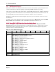
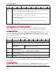
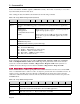
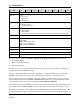
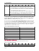
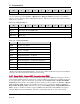
Table Of Contents
- Table of Contents
- 1 Introduction
- 2 Connection Types
- 3 Command Set
- 3.1 About Big Block Data Mode
- 3.2 About SRED / Non-SRED Firmware
- 3.3 About Commands Tagged As “MAC”
- 3.4 General Feature Reports
- 3.4.1 Report 0x01 – Response ACK
- 3.4.2 Report 0x02 – End Session
- 3.4.3 Report 0x03 – Request Swipe Card
- 3.4.4 Report 0x04 – Request PIN Entry
- 3.4.5 Report 0x05 – Cancel Command
- 3.4.6 Report 0x06 – Request User Selection
- 3.4.7 Report 0x07 – Display Message
- 3.4.8 Report 0x08 – Request Device Status
- 3.4.9 Report 0x09 – Set Device Configuration
- 3.4.10 Report 0x09 – Get Device Configuration
- 3.4.11 Report 0x0A – Request MSR Data
- 3.4.12 Report 0x0B – Get Challenge
- 3.4.13 Report 0x0D – Send Session Data - Amount
- 3.4.14 Report 0x0D – Send Session Data - PAN
- 3.4.15 Report 0x0E – Get Information
- 3.4.16 Report 0x0F – Login/Authenticate
- 3.4.17 Report 0x0F – Logout
- 3.4.18 Report 0x10 – Send Big Block Data to Device
- 3.4.19 Report 0x11 – Request Manual Card Entry
- 3.4.20 Report 0x14 – Request User Data Entry
- 3.4.21 Report 0x1A – Request Device Information
- 3.4.22 Report 0x1C – Set/Get BLE Power Configuration (BLE Only)
- 3.4.23 Report 0x1D – Set BLE Module Control Data (BLE Only)
- 3.4.24 Report 0x1E – Set iAP Protocol Info (30-pin Only)
- 3.4.25 Report 0x1E – Get iAP Protocol Info (30-pin Only)
- 3.4.26 Report 0x1F – Request Clear Text User Data Entry
- 3.4.27 Report 0x30 – Set / Get KSN
- 3.4.28 Report 0x31 – Set KSN Encrypted Data
- 3.4.29 Report 0x32 – Set BIN Table Data (MAC)
- 3.4.30 Report 0x32 – Get BIN Table Data
- 3.4.31 Report 0xFF – Device Reset
- 3.5 General Input Reports
- 3.5.1 Report 0x20 – Device State Report
- 3.5.2 Report 0x21 – User Data Entry Response Report
- 3.5.3 Report 0x22 – Card Status Report
- 3.5.4 Report 0x23 – Card Data Report
- 3.5.5 Report 0x24 – PIN Response Report
- 3.5.6 Report 0x25 – User Selection Response Report
- 3.5.7 Report 0x27 – Display Message Done Report
- 3.5.8 Report 0x29 – Send Big Block Data to Host
- 3.5.9 Report 0x2A – Delayed Response ACK
- 3.5.10 Report 0x2B – Test Response
- 3.5.11 Report 0x2D –BLE Module Control Data (BLE Only)
- 3.5.12 Report 0x2E – Clear Text User Data Entry Response Report
- 3.6 EMV-Related Reports
- 3.6.1 Report 0x2C – EMV Cardholder Interaction Status Report
- 3.6.2 Report 0xA1 – Set or Get EMV Tag(s) (MAC)
- 3.6.3 Report 0xA2 – Request Start EMV Transaction
- 3.6.4 Report 0xA4 – Acquirer Response (MAC)
- 3.6.5 Report 0xA5 – Set or Get CA Public Key (MAC)
- 3.6.6 Report 0xA8 – Get Kernel Info
- 3.6.7 Report 0xAB – Request EMV Transaction Data (MAC)
- 3.6.8 Report 0xAC – Merchant Bypass PIN Command
- Appendix A Examples
- Appendix B Terminology
- Appendix C Status and Message Table
- Appendix D MagTek Custom EMV Tags
- Appendix E Configurations
- Appendix F Error Codes
- Appendix G User-Defined Messages
- Appendix H Factory Defaults
- Appendix I Language and Country Codes
- Appendix J BLE Module Control Data
- J.1 BLE Module Configuration Properties
- J.1.1 Get property command
- J.1.2 Set property command
- J.1.3 Software ID property
- J.1.4 Bluetooth Device Address property
- J.1.5 Bluetooth Device Name property
- J.1.6 Configuration Revision property
- J.1.7 Power Timeout property
- J.1.8 Power Control property
- J.1.9 Advertising Control property
- J.1.10 Passkey property
- J.1.11 Desired Minimum Connection Interval Property
- J.1.12 Desired Maximum Connection Interval Property
- J.1.13 Desired Slave Latency Property
- J.1.14 Desired Supervision Timeout Property
- J.1.15 Connection Parameter Update Request Control Property
- J.2 Other Commands
- J.1 BLE Module Configuration Properties

3 - Command Set
DynaPro Mini| PIN Encryption Device | Programmer’s Reference (Commands)
Page 65
device serial number and MAC signature (AMK MAC variant). The format of each entry is one to three
bytes that identify the desired data object.
After sending the data, the USB host should then issue the following command:
Table 3-64 - Usage Table for Report 0xA1 (Get form)
Bit
7
6
5
4
3
2
1
0
Byte 0
0xA1
Byte 1
Specifies which EMV tag group to read: Bits 6 and 7 specify Terminal or Application
group.
00=Terminal
10=Application
11=Dynamic Reader Limits
(DRL)
If bits 6 and 7 are set to Application, bits 0-5 specify the
Application group (0-9) to get.
If bits 6 and 7 are set to DRL, bits 0-5 specify the DRL
group (0-9) to get. Note that DRL applies only to Visa-
PayWave.
Byte 2
Operation:
0x00=Read Operation
0x0F=Read all terminal or payment brand tags
Byte 3
Database Selector:
00 – Contact L2 EMV Tags
01 – PayPass – MasterCard (for future release)
02 – PayWave – VISA (for future release)
03 – ExpressPay – AMEX (for future release)
04 – Discover (for future release)
Byte 4..8
Reserved
If the command is successful, the device will send Report 0x01 – Response ACK, then send Report
0x29 – Send Big Block Data to Host with the EMV tags and requested data. If the device detects a
system error, it will send 0x80 in ACKSTS of Report 0x01 – Response ACK. If the system is not
available, the device will report an error 0x8A in ACKSTS of Report 0x01 – Response ACK.
3.6.3 Report 0xA2 – Request Start EMV Transaction
This command directs the device to prompt the user to confirm transaction amount, and to arm the MSR
and / or contact ICC reader to wait for a card to be swiped or presented into the contact ICC connector. If
armed to read a contact ICC, the device will turn on the LED near the smart card connector after the
cardholder confirms the transaction amount. The host should abort the transaction if the user presses the
CANCEL button.
Table 3-65 - Usage Table for Report 0xA2
Bit
7
6
5
4
3
2
1
0
Byte 0
0xA2
Byte 1
Wait time in seconds, (1 – 60) for cardholder to confirm, cancel, and present card. This
timer is also used for the cardholder to choose an ICC application.
Byte 2
Wait time in seconds, (1 – 60) for cardholder to enter PIN