DynaPro Mini PIN Encryption Device Programmer’s Reference (Commands) July 25, 2014 Manual Part Number: 99875629-2.01 REGISTERED TO ISO 9001:2008 MagTek I 1710 Apollo Court I Seal Beach, CA 90740 I Phone: (562) 546-6400 I Technical Support: (888) 624-8350 www.magtek.
Copyright © 2006 - 2014 MagTek, Inc. Printed in the United States of America Information in this publication is subject to change without notice and may contain technical inaccuracies or graphical discrepancies. Changes or improvements made to this product will be updated in the next publication release. No part of this document may be reproduced or transmitted in any form or by any means, electronic or mechanical, for any purpose, without the express written permission of MagTek, Inc.
LIMITED WARRANTY MagTek warrants that the products sold pursuant to this Agreement will perform in accordance with MagTek’s published specifications. This warranty shall be provided only for a period of one year from the date of the shipment of the product from MagTek (the “Warranty Period”). This warranty shall apply only to the “Buyer” (the original purchaser, unless that entity resells the product as authorized by MagTek, in which event this warranty shall apply only to the first repurchaser).
MagTek’s sole liability and buyer’s exclusive remedies are stated in this section and in the section relating to MagTek’s Limited Warranty. FCC WARNING STATEMENT This equipment has been tested and was found to comply with the limits for a Class B digital device pursuant to Part 15 of FCC Rules. These limits are designed to provide reasonable protection against harmful interference when the equipment is operated in a residential environment.
0 - Table of Contents Table of Contents LIMITED WARRANTY .......................................................................................................................... 3 FCC WARNING STATEMENT .............................................................................................................. 4 FCC COMPLIANCE STATEMENT ........................................................................................................ 4 CANADIAN DOC STATEMENT .......................................
0 - Table of Contents 3.4 General Feature Reports.................................................................................................. 29 3.4.1 Report 0x01 – Response ACK ................................................................................. 29 3.4.2 Report 0x02 – End Session ..................................................................................... 29 3.4.3 Report 0x03 – Request Swipe Card .......................................................................
0 - Table of Contents 3.5.3 Report 0x22 – Card Status Report ......................................................................... 56 3.5.4 Report 0x23 – Card Data Report ............................................................................ 57 3.5.5 Report 0x24 – PIN Response Report ..................................................................... 58 3.5.6 Report 0x25 – User Selection Response Report .................................................. 59 3.5.
0 - Table of Contents F.2 S Codes ............................................................................................................................... 96 F.3 C Codes ............................................................................................................................... 97 F.4 Device Offline K Codes ..................................................................................................... 98 F.5 Device offline A Codes ......................................
0 - Table of Contents DynaPro Mini| PIN Encryption Device | Programmer’s Reference (Commands) Page 9
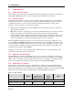
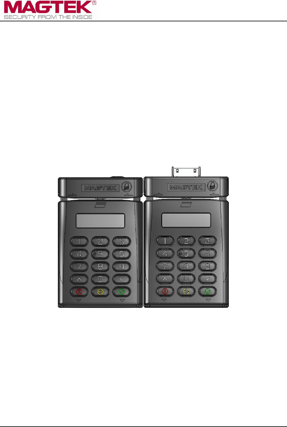
1 - Introduction 1 Introduction 1.1 About This Document This document describes the master command set available through byte-by-byte direct communication with DynaPro Mini PIN encryption devices (referred to in this document as “the device”). 1.2 Nomenclature The general terms “device” and “host” are used in different, often incompatible ways in a multitude of specifications and contexts.
2 - Connection Types Feature User-defined messages IPAD Legacy DynaPro DynaPro Plus DynaPro Plus L1 DynaPro Mini 30-pin DynaPro Mini BLE Yes Yes No No USB connection Yes Yes Yes Yes Ethernet connection No Yes (option) No No Apple 30-pin connection No No Yes No RS-232 connection No No (future option) No No Bluetooth connection (“BLE”) No No No Yes SRED No Yes (option) Yes (option) Yes (option) Non-SRED Yes Yes (option) Yes (option) Yes (option) Smart card contact
2 - Connection Types demonstration software that communicates with the device via this method, and developers can use it to test the device and to provide a starting point for developing other software. For more information, see the MagTek web site, or contact your reseller or MagTek Support Services. These devices are full speed high-powered USB devices that, when connected, draw power from the USB bus. They identify themselves with vendor ID 0x0801 and product ID 0x3009.
2 - Connection Types descriptor byte-by-byte, a full inventory of the report descriptor for these devices is provided in Table 2-1, which also indicates whether each report is a Get type or Set type or both. The reports themselves are fully documented in the sections that follow.
2 - Connection Types Item Value (Hex) Report ID (0x07) - Set 85 07 Usage (Display Message) 09 07 Report Count (2) 95 02 Feature (Data,Var,Abs,NWrp,Lin,Pref,Nnul,Nvol,Buf) B2 02 01 Report ID (0x08) - Set 85 08 Usage (Request Device Status) 09 08 Report Count (1) 95 01 Feature (Data,Var,Abs,NWrp,Lin,Pref,Nnul,Nvol,Buf) B2 02 01 Report ID (0x09) - Get/Set 85 09 Usage (Get/Set Device Config) 09 09 Report Count (8) 95 08 Feature (Data,Var,Abs,NWrp,Lin,Pref,Nnul,Nvol,Buf) B2 02 01 Report
2 - Connection Types Item Value (Hex) Usage (Authenticate/Logout) 09 0F Report Count (9) 95 09 Feature (Data,Var,Abs,NWrp,Lin,Pref,Nnul,Nvol,Buf) B2 02 01 Report ID (0x10) - Set 85 10 Usage (Send Big Block Data to Device) 09 10 Report Count (63) 95 3F Feature (Data,Var,Abs,NWrp,Lin,Pref,Nnul,Nvol,Buf) B2 02 01 Report ID (0x11) - Set 85 11 Usage (Request Manual Card Entry) 09 11 Report Count (3) 95 03 Feature (Data,Var,Abs,NWrp,Lin,Pref,Nnul,Nvol,Buf) B2 02 01 Report ID (0x12) - Set
2 - Connection Types Item Value (Hex) Report Count (63) 95 3F Feature (Data,Var,Abs,NWrp,Lin,Pref,Nnul,Nvol,Buf) B2 02 01 Report ID (0x019) - Get/Set 85 19 Usage (Extended Device) 09 19 Report Count (8) 95 08 Feature (Data,Var,Abs,NWrp,Lin,Pref,Nnul,Nvol,Buf) B2 02 01 Report ID (0x01A) - Get/Set 85 1A Usage (Request Device Configuration) 09 1A Report Count (63) 95 3F Feature (Data,Var,Abs,NWrp,Lin,Pref,Nnul,Nvol,Buf) B2 02 01 Report ID (0x1C) - Get/Set 85 1C Usage (Set/Get BLE Power
2 - Connection Types Item Value (Hex) Input (Data,Var,Abs,NWrp,Lin,Pref,Nnul,Buf) 82 02 01 Report ID (0x22) - Input 85 22 Usage (Card Status) 09 22 Report Count (16) 95 10 Input (Data,Var,Abs,NWrp,Lin,Pref,Nnul,Buf) 82 02 01 Report ID (0x23) - Input 85 23 Usage (Card Data) 09 23 Report Count (127) 95 7F Input (Data,Var,Abs,NWrp,Lin,Pref,Nnul,Buf) 82 02 01 Report ID (0x24) - Input 85 24 Usage (PIN Response) 09 24 Report Count (20) 95 14 Input (Data,Var,Abs,NWrp,Lin,Pref,Nnul,Buf) 8
2 - Connection Types Item Report ID (0x2B) - Input Value (Hex) 85 2B RESERVED Report ID (0x2C) - Input 85 2C Usage (EMV Cardholder Interaction Status) 09 2C Report Count (127) 95 7F Input (Data,Var,Abs,NWrp,Lin,Pref,Nnul,Buf) 82 02 01 Report ID (0x2D) - Input 85 2D Usage (BLE Module Control Data) 09 2D Report Count(64) 95 40 Input (Data,Var,Abs,NWrp,Lin,Pref,Nnul,Buf) 82 02 01 Report ID (0x2E) - Input 85 2E Usage (Clear Text User Data Entry Response Report) 09 2E Report Count (12) 95
2 - Connection Types Item Value (Hex) Feature (Data,Var,Abs,NWrp,Lin,Pref,Nnul,Buf) B2 02 01 Report ID (0xA2) - Set 85 A2 Usage (Request Start EMV Transaction) 09 A2 Report Count (48) 95 30 Feature (Data,Var,Abs,NWrp,Lin,Pref,Nnul,Buf) B2 02 01 Report ID (0xA3) - Set 85 A3 Usage (Request ATR Data) 09 A3 Report Count (1) 95 01 Feature (Data,Var,Abs,NWrp,Lin,Pref,Nnul,Buf) B2 02 01 Report ID (0xA4) - Set 85 A4 Usage (Acquirer Response) 09 A4 Report Count (12) 95 0C Feature (Data,Var,
2 - Connection Types Item Value (Hex) Report ID (0xAA) - Set 85 AA Usage (Confirm Session Key) 09 AA Report Count (17) 95 11 Feature (Data,Var,Abs,NWrp,Lin,Pref,Nnul,Buf) B2 02 01 Report ID (0xAB) - Set 85 AB Usage (Request EMV Transaction Data) 09 AB Report Count (4) 95 04 Feature (Data,Var,Abs,NWrp,Lin,Pref,Nnul,Buf) B2 02 01 Report ID (0xAC) - Set 85 AC Usage (Merchant Bypass PIN Command) 09 AC Report Count (1) 95 01 Feature (Data,Var,Abs,NWrp,Lin,Pref,Nnul,Nvol,Buf) B2 02 01 Re
2 - Connection Types Bit 7 Byte 1..n 6 5 4 3 2 1 0 Command/Response as defined in section 3 Command Set. IMPORTANT: Generally, iOS commands must be transmitted in MSB (big endian) order. By convention, this document gives commands in LSB (little endian) order. 2.3 How to Use BLE Connections This section provides information about developing software for a BLE-capable host that needs to interface with the device using Bluetooth Low Energy (BLE).
2 - Connection Types 7) Send commands to the device by writing to the Application Data From Host Length characteristic, then to the Application Data From Host characteristic; receive notifications that the device has changed the Application Data To Host Length characteristic, and read the corresponding incoming data from the Application Data To Host characteristic. 8) The device will stay powered on until the host terminates the BLE connection, or until a user powers off the device using the power switch.
2 - Connection Types Response from Device Byte 0 1 (Response ACK Report ID) Byte 1..2 (Response ACK Report) Input report format Byte 0 Report ID Byte 1 - n Report Maximum report size is 127 bytes.
3 - Command Set 3 Command Set This section describes the full device command set. Because the command set is common to all connection types, it is helpful to first read and understand section 2.1.1 About HID Usages to become familiar with the types of available commands. 3.
3 - Command Set 3.3 About Commands Tagged As “MAC” All commands and responses in this chapter that are tagged “MAC” require the host to calculate and append the device unique serial number and a MAC signature to the message per ANSI X9.19 -1996 – Financial Institution Retail Message Authentication. Data for “MAC” commands is staged using big block data buffers. For information about using big block mode, section 3.1 About Big Block Data Mode.
3 - Command Set DFDF3C DFDF3D DFDF43 DFDF50(MSR KSN Data) /*sent in the clear*/ DFDF51(MSR EncryptionType) F5/* container tag for encrypted PIN data (normally debit card)*/ 99(Encrypted PIN DATA) DFDF41(PIN KSN Data) DFDF42(PIN EncryptionType) (Buffer if any to be a multiple of 8 bytes) CBC-MAC (4 bytes, use MAC variant of MSR DUKPT key) 3.3.2.
3 - Command Set DFDF3D DFDF43 DFDF50(MSR KSN Data) /*sent in the clear*/ DFDF51(MSR EncryptionType) F5/* container tag for encrypted PIN data */ 99(Encrypted PIN DATA) DFDF41(PIN KSN Data) DFDF42(PIN EncryptionType) 3.3.2.3 ARQC Response (Report 0xA4 – Acquirer Response) Response from host (key used must be the same as KSN in ARQC request).
3 - Command Set CBC-MAC (4 bytes, use MAC variant of MSR DUKPT key) 3.3.3.2 SRED Batch Data Begin with a two-byte header in big-endian form (MSB first) that contains the expected length of the message after decryption, excluding data padding and CBC-MAC. Use container F9 for the MAC structure, use F8 within FA for passing encrypted batch data message, use MAC variant of MSR DUKPT key.
3 - Command Set 3.4 General Feature Reports 3.4.1 Report 0x01 – Response ACK This command causes the device to send the host a response status (“ACKSTS”, see Appendix C Status and Message Table), and the Report ID of the command the host has just executed. The host should get this report immediately after it sends any command to the device to determine whether or not the device accepted the command as sent.
3 - Command Set 3.4.3 Report 0x03 – Request Swipe Card This command causes the device to prompt the user to swipe a card by displaying one of four predetermined messages (see Card Message ID in Table 3-3).
3 - Command Set 3.4.4 Report 0x04 – Request PIN Entry This command causes the device to prompt the user to enter a PIN by displaying one of five predetermined messages (see PIN Mode in Table 3-4).
3 - Command Set Bit 7 Byte 4 Tones: 0 = No sound 1 = One beep 2 = Two beeps Byte 5 PIN options 6 5 4 RESERVED DynaPro Mini| PIN Encryption Device | Programmer’s Reference (Commands) Page 32 3 2 Wait Msg 1 0 Verify PIN ISO3
3 - Command Set 3.4.5 Report 0x05 – Cancel Command This command cancels the current command. Table 3-5 - Usage Table for Report 0x05 Bit 7 Byte 0 0x05 Byte 1 0 6 5 4 3 2 1 0 3.4.6 Report 0x06 – Request User Selection This command causes the device to prompt the user to select the transaction type (debit, credit, etc.
3 - Command Set Bit Byte 4 7 6 5 4 3 2 Enter Right 1 Middle 0 Left Tones: Start Transaction Tones Only: 0 = No sound 1 = One beep 2 = Two beeps Start Transaction & Timeout Tones: 100 = No start beep, no timeout 101 = One start beep, no timeout 102 = Two start beep, no timeout 3.4.7 Report 0x07 – Display Message This command causes the device to display a predefined message for a specified time. Examples are shown below.
3 - Command Set Bit Byte 2 7 6 5 4 3 2 1 0 Display message ID: 0 = Blank 1 = Approved 2 = Declined 3 = Cancelled 4 = Thank You 5 = PIN Invalid 6 = Processing 7 = Please Wait 8 = Hands Off 9 = PIN PAD not available 10 = Call Your Bank 11 = CARD ERROR 12 = Not Accepted 13 = Processing Error 14 = Use CHIP Reader 15 = Refer to your payment device 3.4.8 Report 0x08 – Request Device Status This command causes the PIN-PAD to send current information (Session State, Device State and Status, etc.
3 - Command Set Bit 7 6 5 4 3 Config 0=unlocked 1=locked Bitmap 0=unlocke d 1=locked Tests Allowed 0=disable 1=enable iAP Config Allowed 0=unlocked 1=locked Clear Text User Data 0=no 1=yes 2 0 Byte 2 Allow Charging in iAP mode 0x00 = disabled, default 0x01 = enabled Byte 3 Mask Configuration (default value = 0xC0, all enabled except MS2.0) ISO Mask 0 = disable 1 = enable Byte 4 Check Digit 0 = disable 1 = enable MS2.0 Enable 00 = MS2.0 disabled 10 = MS2.
3 - Command Set If Error = 1, the device will not build MS2.0 format track data (if MS2.0 is enabled) if the indicated track contains error(s). If Blank = 0, the device will build MS2.0 format track data (if MS2.0 is enabled) if at least one track contains good data – the indicated track may be blank. If Blank = 1, the device will not build MS2.0 format Track data (if MS2.0 is enabled) if the indicated track is blank. 3.4.
3 - Command Set Bit Byte 7 7 6 5 4 3 2 1 0 EMV L2 ICS Configuration (Default = 0x01) Note: This setting is ignored when EMV Mode is disabled. EMV L2 ICS Configuration 0000 = No L2 capability 0001 = Configuration 1C 0010 = Configuration 2C 0011..1111 = Reserved Byte 8 0x00 3.4.11 Report 0x0A – Request MSR Data This command causes the device to send MSR data to the host; it should be issued after a Report 0x03 – Request Swipe Card command has successfully completed.
3 - Command Set After sending this command to the device and getting the ACKSTS report, the host should issue this command in Get mode. If the key ID is not in the list, or a valid authentication key is not available for key ID = 0x63, the data block will be all zeros.
3 - Command Set Bit 7 6 5 Byte 4..14 Amount data in ASCII format Byte 15..21 Reserved 4 3 2 1 0 3.4.14 Report 0x0D – Send Session Data - PAN This command is used to send card PAN data to the device in cases where the PAN is coming from a source other than the card being processed.
3 - Command Set Bit 7 6 5 4 Byte 2 Key Status, if Info ID < 0x80: 0 = Empty (default) 1 = OK 2 = Exhausted Key Status, if Info ID = 0x80: 0 – 5 = KCV type (see Table 3-18) Byte 3 Data length (see Table 3-18); default value is 0 Byte 4..
3 - Command Set Info ID Key Status Data length Data Description 0x50 1 9 Keypad sensitivity Tamper sensitivity Key on threshold Key off threshold 4 bytes keypad threshold Keypad calibration result Keypad values 0x51 1 8 Parameter1 (2 bytes) Parameter2 (2bytes) Z ON pen (1 byte) Z OFF pen (1 byte) Reserved for future use (2 bytes) Signature Capture configuration 0x60 – 0x70 1 <=59 SN & subject’s DN** If associated CA cert exists*** 0x71 – 0x7F 1 <=59 SN & issuer’s DN** If associated C
3 - Command Set 3.4.16 Report 0x0F – Login/Authenticate This command logs in the device.
3 - Command Set Data length error (e.g., the data size is 0 or is larger than the available buffer size) (0x83) If the command is successful, the bitmap image or key handling/manufacturing command will be stored in a predefined buffer within the device. If the Data Type byte is set to one of the types tagged “Secured,” the first 2 bytes of the data packet should be the expected length of the message after decryption.
3 - Command Set Bit 7 6 5 4 3 2 1 Byte 3 Packet length Byte 4..63 Packet data: For EMV data, use Tag-Length-Value format [for examples, see section 3.3 About Commands Tagged As “MAC”] 0 3.4.19 Report 0x11 – Request Manual Card Entry This command causes the device to prompt the user to enter the following card information by keypad.
3 - Command Set Bit 7 6 5 4 3 Byte 1 Wait Time in seconds, (1 – 255; 0 = 256 seconds) Byte 2 0 0 0 0=Use PAN min 9, max 19 1=Use PAN min 14, max 21 Byte 3 1=Use PAN in PIN block creation 2 1=Use Qwick Codes entry 1 0 Field Options: 0 = Acct,Date,CVC 1 = Acct,Date 2 = Acct,CVC 3 = Acct Tones: 0 = No sound 1 = One beep 2 = Two beeps The track data sent by the device for manually entered card data may be masked according to the device’s configuration (the same as it is for credit/debit card
3 - Command Set transaction. If data entry is successful, the report will also contain the MSR KSN and the encrypted user data block (EUDB). The EUDB format is similar to the PIN ISO format 1 data block. The EUDB is encrypted using X9.24 data variant under the current data variant derived from the MSR key.
3 - Command Set Bit Byte 2..63 7 6 5 4 3 2 1 0 “3004” (null terminated string) Table 3-27 - Usage Table for Report 0x1A - Maximum Application Message Size Bit 7 6 Byte 0 0x1A Byte 1 0x01 Byte 2 to 63 “64” (null terminated string) 5 4 3 2 1 0 4 3 2 1 0 Table 3-28 - Usage Table for Report 0x1A – Capability String Bit 7 6 5 Byte 0 0x1A Byte 1 0x02 Byte 2..
3 - Command Set Table 3-32 - Usage Table for Report 0x1A - Firmware Number Bit 7 6 5 4 Byte 0 0x1A Byte 1 0x06 Byte 2..63 “30050856A01-DEMO” (null terminated string) 3 2 1 0 3 2 1 0 3 2 1 0 3 2 1 0 Table 3-33 - Usage Table for Report 0x1A – Build Info Bit 7 6 5 Byte 0 0x1A Byte 1 0x07 Byte 2..63 “
3 - Command Set 3.4.22 Report 0x1C – Set/Get BLE Power Configuration (BLE Only) This command sets or gets the BLE power configuration, depending on whether it is called in Set mode or Get mode.
3 - Command Set Table 3-37 – Usage Table for Report 0x1D Bit 7 6 5 4 Byte 0 0x1D (report identifier) Byte 1 Control data length (defined in Appendix J) Byte 2 to (2+control data length-1) Control data (defined in Appendix J) Byte (2 + control data length) to 63 Padding. Set all bytes to zero. 3 2 1 0 1 0 3.4.24 Report 0x1E – Set iAP Protocol Info (30-pin Only) When the host calls this command in Set mode, it sets iAP related data in the device.
3 - Command Set Otherwise, when the command completes (data entry done, user cancelled, or timeout), the device will send Report 0x2E – Clear Text User Data Entry Response Report to the host using a USB Interrupt IN transaction. If data entry is successful, the report will also contain the requested data.
3 - Command Set Bit 7 6 5 Byte 2..11 Data block: Byte 2 – Byte 11 contain the KSN Byte 12..19 Device Serial Number Byte 20..23 Padding Byte 24..27 CBC-MAC 4 3 2 1 0 3.4.28 Report 0x31 – Set KSN Encrypted Data Before using this command, the host must have already used Report 0x30 – Set / Get KSN to retrieve the MSR dukpt KSN from the device.
3 - Command Set 3.4.29 Report 0x32 – Set BIN Table Data (MAC) The device provides six slots in the BIN table to hold BINs. Each slot holds 6 digits. After a cardholder swipes a card, the device will check the BIN table to see if it contains the card’s BIN. If it finds the card’s BIN and if the card’s PAN length is 19 characters or longer, it will not encrypt data ID 4, 5 or 6 in the Report 0x23 – Card Data Report it sends to the host.
3 - Command Set Bit 7 6 Byte 26..31 Data on BIN Table Slot 5 Byte 32..37 Data on BIN Table Slot 6 5 4 3 2 1 0 An error will be reported in ACKSTS of Report 0x01 – Response ACK in the following cases: Bad parameter (0x82) System is not available (0x8A) 3.4.31 Report 0xFF – Device Reset This command causes the device to perform a restart. Table 3-46 – Usage Table for Report 0xFF Bit 7 Byte 0 0xFF Byte 1 0 – Soft Reset Byte 2 Reserved 3.
3 - Command Set 3.5.2 Report 0x21 – User Data Entry Response Report This event supports Report 0x14 – Request User Data Entry. After the user has successfully entered data, the device uses this report to send user data to the host. Table 3-48 - Usage Table for Report 0x21 Bit 7 6 5 4 3 2 Byte 0 0x21 Byte 1 Operation Status (see Appendix C Status and Message Table) Bytes 2..11 MSR KSN Bytes 12..
3 - Command Set Bit Byte 3 7 6 5 4 3 2 1 0 Card Type (see Appendix C Status and Message Table) 3.5.4 Report 0x23 – Card Data Report This event is triggered by Report 0x0A – Request MSR Data, which causes the device to send eight reports to the host for each successful card swipe or manual card entry.
3 - Command Set Table 3-52 - Report 0x23 Track Status Byte When Using MS2.0 Masking Value Track Status If Using MS2.
3 - Command Set Bit 7 6 5 4 Bytes 2..11 PIN KSN. If fixed PIN key is used, KSN is zero. Bytes 12..19 Encrypted PIN block 3 2 1 0 3.5.6 Report 0x25 – User Selection Response Report This event is triggered when the user is asked to choose an account type, which causes the device to send the user’s response (i.e. the key pressed) to the host.
3 - Command Set Bit 7 6 5 4 3 2 1 Byte 1 Big buffer type: 0x00 = Signature capture data 0x02 = Device cert 0x18 = Perform Test (0x18) APDU 0x32 = Set BIN 0x42 = CSR 0xA1 = EMV data in TLV format, Tag Data (MAC) 0xA2 = RESERVED 0xA3 = RESERVED 0xA4 = EMV data in TLV format, Authorization Request (ARQC) 0xA5 = CA Public Key (MAC) 0xA6 = ATR (Secured) 0xA7 = R-APDU (Secured) 0xAB = EMV data in TLV format, Batch Data or Batch Data and Reversal Data Byte 2 0x00 = Start flag Byte 3 Big buffer status
3 - Command Set Tag Description Source Format Length 9F03 Secondary amount associated with the transaction representing a cash back amount Device n 6 9F26 Cryptogram returned by the ICC in response of the GENERATE AC command Card b 8 82 Application Interchange Profile Card b 2 5A Application PAN Card c 0-10 5F34 Application PAN Sequence Number Card n 1 9F36 Application Transaction Counter Card b 2 9F1A Terminal Country Code Device n 2 95 TVR Device b 5 9F02 Auth
3 - Command Set Important usage notes regarding getting and setting BLE module properties are included in section 3.4.23 Report 0x1D – Set BLE Module Control Data (BLE Only). Table 3-60 - Usage Table for Report 0x2D Byte Description Byte 0 0x2D Byte 1 Control data length (defined in Appendix J) Bytes 2 to (2 + control data length – 1) Control data (defined in Appendix J) Bytes (2 + control data length) to 63 Padding. All bytes are zeros. 3.5.
3 - Command Set 3.6 EMV-Related Reports This section contains both commands sent from the host to the device (feature reports) and asynchronous events sent from device to the host (input reports) that support EMV transaction processing. After the device successfully reads a smart card, it generates EMV data in the form of tags for transaction processing. The device then sends the host its own information plus information read from the card.
3 - Command Set Bit Byte 4..127 7 6 5 4 3 2 1 0 Data block: If EMV Cardholder Interaction Status ID from Byte 1 = 0x02, value 0x1 indicates Amount Confirmed, or value 0x2 indicates Amount Not Confirmed. If EMV Cardholder Interaction Status ID from Byte 1=0x04, data is a string representing application preferred name, or label chosen by cardholder.
3 - Command Set device serial number and MAC signature (AMK MAC variant). The format of each entry is one to three bytes that identify the desired data object. After sending the data, the USB host should then issue the following command: Table 3-64 - Usage Table for Report 0xA1 (Get form) Bit 7 6 5 4 3 2 1 0 Byte 0 0xA1 Byte 1 Specifies which EMV tag group to read: Bits 6 and 7 specify Terminal or Application group.
3 - Command Set Bit 7 6 5 4 3 2 1 0 Byte 3 0, Reserved Byte 4 Tones: 0 = No sound 1 = One beep 2 = Two beeps Byte 5 Card Type to Read: 1 = Magnetic Stripe 2 = Contact smart card Byte 6 Options: 1 = Bypass PIN 2 = Force Online 4 = Acquirer not available (Note: prevents long timeout on waiting for host approval) Byte 7..
3 - Command Set ICC, and will advise the cardholder that ICC is preferred by displaying USE CHIP READER. If the ICC fails or the service code does not begin with a 2 or a 6, the device will prompt the cardholder for an MSR swipe. After a successful swipe, the device will prompt the user to select debit or credit. If this is a debit account type, the device will request a PIN.
3 - Command Set Report 0x10 – Send Big Block Data to Device is first used to send the Acquirer Response Data with the device serial number and signed with the current MSR MAC variant key to the device. After sending the data, issue the following command: Table 3-66 - Usage Table for Report 0xA4 Bit 7 6 Byte 0 0xA4 Byte 1..12 Reserved 5 4 3 2 1 0 3.6.5 Report 0xA5 – Set or Get CA Public Key (MAC) This command causes the device to load, erase or read CA Public Key(s).
3 - Command Set Bit 7 6 5 4 3 2 1 0 Byte 1 Operation: 0 – Erase All CA Public Keys (No Additional Data from Report 0x10 needed) 1 – Erase All CA Public Keys for a given RID (Report 0x10 provides a single RID only) 2 – Erase a single CA Public Key (Report 0x10 provides one RID and RID key Index only) 3 – Add a CA Public Key (Report 0x10 provides all data) 4 – Read a single CA Public Key (Report 0x10 provides one RID and RID key Index only) 0x0F – Read all CA Public key(s).
3 - Command Set Bit Byte 1 7 6 5 4 3 2 1 0 Kernel Info ID (see Table 3-71) An error will be reported in ACKSTS of Report 0x01 – Response ACK if the system is not available (0x8A) or if the command contains bad parameters (0x82). Otherwise, the device will send the following input report to the host: Table 3-70 - 0xA8 Input Report Bit 7 6 5 Byte 0 0xA8 Byte 1 Kernel Info ID (see Table 3-71) Byte 2 Data length Byte 3..
3 - Command Set Table 3-72 - Usage Table for Report 0xAB Bit Byte 0 7 6 5 4 3 2 1 0 0xAB Byte 1..4 00 – Reserved Return data in the big block will use the EMV tag 0xF0 as the container tag for status, batch data, reversal data, and merchant data as shown.
3 - Command Set Table 3-73 - Big Block Response to Report 0xAB - Status Data Container (F1) Tag Description Source Format Length (decimal) DFDF1A Transaction Status 0x00 = Accept 0x01 = Decline 0x02 = Error 0x10 = Cancelled by Host 0x11 = Confirm Amount No 0x12 = Confirm Amount Timeout 0x13 = Confirm Amount Cancel 0x14 = MSR Select Credit 0x15 = MSR Select Debit 0x16 = MSR Select Credit/Debit timeout 0x17 = MSR Select Credit/Debit cancel 0x18 = Signature Capture Cancelled by Host 0x19 = Signature Cap
3 - Command Set Table 3-74 - Big Block Response to Report 0xAB - Batch Data Container (F2 [Default Tags Shown]) Tag Description Source Format Length (decimal) 82 Application Interchange Profile Card b 2 8E CVM list Card b 0-252 5F24 Date after which the Application expires Card n 3 5F25 Date from which the Application can be used Card n 3 9F06 Indicates the Application as described in ISO/IEC 7816-5 Device b 5-16 9F07 Indicates issuer's specified restrictions on the geographi
3 - Command Set Tag Description Source Format Length (decimal) 9F37 Value to provide variability and uniqueness to the generation of a cryptogram Device b 4 9F40 Additional Terminal Capabilities Device b 5 DFDF70 TAC-default (Terminal Action Codes) Device n 5 DFDF71 TAC-Offline (Terminal Action Codes) Device n 5 DFDF72 TAC-Online (Terminal Action Codes) Device n 5 9F5B Issuer Script Results Device b 0-128 The Merchant Data (F7) Container is included in the response to Repo
3 - Command Set Tag Description Source Format Length (decimal) 9F34 Indicates the results of the last CVM performed Device b 3 5F57 Account Type Device N2 1 5F34 PAN Sequence Number ICC N2 1 The Reversal Data (F3) Container may be included in the response to Report 0xAB – Request EMV Transaction Data normally used by the host for reversal processing.
3 - Command Set Tag Description Source Format Length 9F02 Amount Authorized Device n 6 5F2A Transaction Currency Code Device n 2 9A Transaction Date Device n 3 9F21 Transaction Time Device n 3 9C Transaction Type Device n 1 3.6.8 Report 0xAC – Merchant Bypass PIN Command This command allows the host to bypass the PIN entry requirement during an EMV transaction (Report 0xA2 – Request Start EMV Transaction).
Appendix A - Examples Appendix A A.1 Examples How to Get MSR/PIN Data from the Device for a Bank Simulation This section provides a byte-for-byte example of transmitting commands using the USB connection and the Apple 30-pin connection. All data shown in this section is in hexadecimal format.
Appendix A - Examples 20 02 08 40 47 07 iOS format of command (Note MSB order) 4) After the cardholder swipes the card, the device sends back Report 0x22 – Card Status Report to the host, which expands to the following bytes: a) 22: Report ID (22=Report 0x22 – Card Status Report) b) 00: Operation status (00=OK) c) 00: Card status (00=OK) d) 01: Card type (01=Financial card) Sample Report 0x22 – Card Status Report 22 00 00 01 USB format of command 22 00 00 01 iOS format of command (Note MSB order) 5)
Appendix A - Examples g) 01: PIN option (01=ISO3) Sample Report 0x04 04 1E 00 44 01 01 USB format of command 01 04 1E 00 44 01 01 iOS format of command (Note MSB order) 10) The device sends the host Report 0x01 – Response ACK if the command is successful. 11) The device sends the host Report 0x24 – PIN Response Report if PIN entry is successful. 12) The device sends the host another Report 0x20 – Device State Report.
Appendix B - Terminology Appendix B Terminology This appendix provides definitions of common terms used in this document.
Appendix B - Terminology Term Definition DOL Data Object List DUKPT Derived Unique Key Per Transaction. A key management scheme in which a unique key is used for every transaction CBC Cipher Block Chaining EMV[co] Europay MasterCard Visa [company] EPB Encrypted PIN Block GATT Generic ATTribute Profile, a general specification for sending and receiving short pieces of data known as "attributes" over a BLE link.
Appendix B - Terminology Term Definition PAN Personal Account Number, which is most commonly recognized as the 16-digit user account number associated with a card. PCI DSS Payment Card Industry Data Security Standards PCI PED Payment Card Industry PIN Entry Device PED Pin Encryption Device, the generic term for the class of devices that includes IPAD, DynaPro, and DynaPro Mini. PIN Personal Identification Number PKI Public Key Infrastructure.
Appendix C - Status and Message Table Appendix C Status and Message Table Table 3-79 - Status and Message Codes Status/Message Value Operation Status 0x00 = OK / Done 0x01 = User Cancel 0x02 = Timeout 0x03 = Host Cancel 0x04 = Verify fail 0x05 = Keypad Security 0x06 = Calibration Done 0x07 = Write with duplicate RID and index 0x08 = Write with corrupted Key 0x09 = CA Public Key reached maximum capacity 0x0A = CA Public Key read with invalid RID or Index ACK Status (“ACKSTS”) 0x00 = OK / Done 0x80 =
Appendix C - Status and Message Table Status/Message Value EMV Message EMV 4.3 BOOK 4 Section 11.2 “Standard Messages.
Appendix C - Status and Message Table Status/Message Value Device State 0x00 = Idle 0x01 = Session 0x02 = Wait For Card 0x03 = Wait For PIN 0x04 = Wait For Selection 0x05 = Displaying Message 0x06 = Test (Reserved for future use) 0x07 = Manual Card Entry 0x08 = Wait for Signature Capture 0x09 = Wait User Entry 0x0A = Smart Card 0x0B = ICC Kernel Test 0x0C = EMV Transaction 0x0D = Show PAN Card Type 0x00 = Other 0x01 = Financial 0x02 = AAMVA 0x03 = Manual 0x04 = Unknown 0x05 = ICC Card Status 0x00 = O
Appendix D - Status and Message Table Status/Message Device Status Session State Device Certificate Status Hardware Status Value 0x00 = OK Otherwise, the possible values are listed below: System – 1 = System Error (EndSession clears) Auth – 1 = Not Authorized (cleared when device is authenticated) Tamper – 1 = Tamper Detected MSR – 00 = OK – 01 = No MSR Key – 10 = MSR Key Exhausted – 11 = MSR Key not Bound PIN – 00 = OK – 01 = No PIN Key – 10 = PIN Key Exhausted – 11 = PIN Key not Bound Bit 7 6 5 4
Appendix D - MagTek Custom EMV Tags Appendix D MagTek Custom EMV Tags In addition to the standard EMV tags documented in EMV 4.3, Book 3, Annex A, MagTek provides additional custom tags with the device, which are listed in Table 3-80. The characters used in the “Format” column are described in EMV 4.3, Book 4, Section 4.3.
Appendix D - MagTek Custom EMV Tags Tag Description Default (HEX) Forma t Length DFDF05 Reversal Tags 82 9F 36 9F 1E 9F 10 9F 5B 9F 33 9F 35 95 9F 01 5F 24 5A 5F 34 8A 9F 15 9F 16 9F 39 9F 1A 9F 1C 57 9F 02 5F 2A 9A 9F 21 9C b var up to 123 DFDF06 Authorization Response Tags 8A 91 b var up to 123 DFDF07 Certification Validation Table (Not supported) 00 b 1 DFDF10 Threshold Value for Biased Random Selection 00 00 00 00 40 00 N 6 DFDF11 Target Percentage to be used for Random Selecti
Appendix D - MagTek Custom EMV Tags Tag Description Default (HEX) Forma t Length DFDF22 PSE Name 31 50 41 59 2E 53 59 53 2E 44 44 46 30 31 b 14 DFDF23 ASI (Application Select Indicator) 01 b 1 DFDF24 Requested Transaction Type * b 1 DFDF25 Unique and permanent serial number assigned to the IFD by the manufacturer USIP SN b 8 DFDF26 Reader & Application Database Label b 16 DFDF27 Reader & Application Database Checksum b 20 DFDF28 CAPK Database Label b 16 DFDF29 CAPK Data
Appendix D - MagTek Custom EMV Tags Tag Description Default (HEX) Forma t Length DFDF42 PIN Encryption Type: 0xxx xxxx = Fixed key 1xxx xxxx = DUKPT key xx00 xxxx = TDES xx01 xxxx = AES xxxx xx00 = Data variant xxxx xx01 = PIN variant xxxx xx10 = MAC variant * b 1 DFDF43 MagnePrint Status Data * b 4 DFDF44 Encrypted PAN Data * b var DFDF50 MSR KSN * b 10 DFDF51 MSR Encryption Type (see DFDF42 for bit definitions) * b 1 DFDF52 Card Status (Report 0x22) (Not supported) - - -
Appendix D - MagTek Custom EMV Tags Tag Description Default (HEX) Forma t Length DFDF71 Terminal Action Code - Denial 00 00 00 00 00 00 b 5 DFDF72 Terminal Action Code - Online 00 40 00 00 00 00 b 5 DFDF73 Payment Brand Account Type (0 - Unknown, 0x01-Credit or Debit, 0x02-Debit, 0x03-Credit) 00 b 1 * - Value is based on the ongoing transaction DynaPro Mini| PIN Encryption Device | Programmer’s Reference (Commands) Page 91
Appendix E - Configurations Appendix E E.1 Configurations PIN-PAD Terminal Configuration Characteristics Physical: Keypad PINPad Display Yes Printer No MSR Yes IC reader Yes Functional: Language Selection Yes Transaction Type Goods, Services & Cash back SDA, DDA Yes CVM Online/Offline PIN Card Capture No Online Capable Thru host Offline Capable Yes Per Annex A of EMV 4.3 Book 4. E.
Appendix E - Configurations b8 b7 b6 b5 b4 b3 b2 b1 Meaning x x x x x x 0 x RFU x x x x x x x 0 RFU Table 3-82 - Byte 2: CVM Capability = 0xE8 (ICS Config 1), 0xB8 (ICS Config 2) b8 b7 b6 b5 b4 b3 b2 b1 Meaning 1 x x x x x x x Plaintext PIN for ICC verification x 1 or 0 x x x x x x Enciphered PIN for online verification x X 1 x x x x x Signature (paper) x x x 1 x x x x Enciphered PIN for offline verification x x x x 1 x x x No CVM Required
Appendix E - Configurations Table 3-84 - Byte 1: Transaction Type Capability 1 = 0x70 b8 b7 B6 B5 b4 b3 b2 b1 Meaning 0 x x X x x x x Cash x 1 x X x x x x Goods x x 1 X x x x x Services x x x 1 x x x x Cash back x x x x 0 x x x Inquiry x x x x x 0 x x Transfer x x x x x x 0 x Payment x x x x x x x 0 Administrative Table 3-85 - Byte 2: Transaction Type Capability 2 = 0x00 b8 b7 b6 b5 b4 b3 b2 b1 Meaning 0 x x x x x x x Cash
Appendix E - Configurations Table 3-87 - Byte 4: Terminal Data Output Capability 3 = 0xB0 b8 b7 b6 B5 b4 b3 b2 b1 Meaning 1 x x x x x x x Print, attendant X 0 x x x x x x Print, cardholder X x 1 x x x x x Display, attendant X x x 1 x x x x Display, cardholder X x x x 0 x x x RFU x x x x x 0 x x RFU x x x x x x 0 x Code table 10 x x x x x x x 0 Code table 9 The code table number refers to the corresponding part of ISO/IEC 8859.
Appendix F - Error Codes Appendix F F.
Appendix F - Error Codes Code Calculated Sn where n = sum of the following Description Meaning +2 Keypad calibration not complete (Status stored in BPK) After reset, calibration should be redone (but really only status has been lost) +4 MSR key pairing not completed Need to perform action. Permanent. +8 Tamper sensors not activated Status set after BPK initialized. Cleared once sensors activated. Stored in BPK +16 Keypad activation sequence not sent Need to perform action. Permanent.
Appendix F - Error Codes Code Calculated Cn where n = sum of the following +16 Description Device certificate does not exist F.
Appendix G - User-Defined Messages Appendix G User-Defined Messages This appendix describes how the host can define user-defined messages on the device. Start by creating a block of user-defined message data (see Table 3-95) containing one or more user data strings, and send it to the device using Report 0x10 – Send Big Block Data to Device. The messages are then available when using the Select or Display commands.
Appendix H - User-Defined Messages ~~~ MemoryStream ms = new MemoryStream(); ms.WriteByte(4); // # of strings addUserString(ms, 19, 56, 0x25, 0, "$20"); addUserString(ms, 64, 56, 0x25, 0, "$40"); addUserString(ms, 112, 56, 0x25, 0, "$100"); addUserString(ms, 64, 30, 0x15, 0, "Select Cashback"); pp.SendMultiData(6, ms.ToArray()); //6 for getsel, 7 for disp pp.GetResponse(30, ResponseMsg.UserMsg, KeyMask.Left | KeyMask.Right | KeyMask.
Appendix H - Factory Defaults Appendix H H.
Appendix H - Factory Defaults Tag Description Tag Configurable Certification Validation Table 0xDFDF07 Not supported 00 Default CVM 0xDFDF13 Acquirer 01 Socket Timeout 0xDFDF14 Acquirer 00 00 0B B8 Socket Retries 0xDFDF15 Acquirer 00 00 00 01 Issuer Script Max Size 0xDFDF16 Compile Only 00 00 00 80 Batch Data Tags 0xDFDF17 Acquirer 82 8E 5F 24 5F 25 9F 06 9F 07 9F 0D 9F 0E 9F 0F 9F 10 9F 26 9F 27 9F 36 95 9B 9C 9F 33 9F 34 9F 37 9F 40 DF DF 70 DF DF 71 DF DF 72 9F 5B Default Termi
Appendix H - Factory Defaults Tag Description Tag Configurable Default Value(hex) DDOL 0x9F49 Acquirer 9F 37 04 5A 08 5F 34 01 9A 03 ASI (Application Select Indicator) 0xDFDF23 Acquirer 01 Application Version 0x9F09 Acquirer 00 8C TAC – Default 0xDFDF70 Acquirer 00 00 00 00 00 TAC – Denial 0xDFDF71 Acquirer 00 00 00 00 00 TAC – Online 0xDFDF72 Acquirer 00 40 00 00 00 Payment Brand Account Type 0xDFDF73 Acquirer 03 Terminal Threshold Value 0xDFDF10 Acquirer 00 00 00 00 40 0
Appendix I - Language and Country Codes Appendix ILanguage and Country Codes The device’s language and country codes are derived from ISO 3166-1; country codes are numeric, and language codes are ASCII strings based on alpha-2. I.1 Terminal Country Codes Table 3-99 - Terminal Country Codes 0840 United States 0250 France 0380 Italy 0724 Spain 0276 Germany I.
Appendix J - BLE Module Control Data Appendix J BLE Module Control Data This section defines control messages that can be sent to the device’s BLE module.
Appendix J - BLE Module Control Data Set Property: No Default value: None Description: This is the 11 byte read-only property that identifies the software part number and version for the device. The first 8 bytes represent the part number and the last 3 bytes represent the version. For example this string might be “30050884A01”. This string is subject to change. Example Get Software ID property: Request message (hex): 00 00 00 Response message (hex): 01 00 33 30 30 35 30 38 38 34 41 30 31 J.1.
Appendix J - BLE Module Control Data Example Get Bluetooth Device Name property: Request message (hex): 00 00 02 Response message (hex): 01 00 31 32 33 (device name “123”) Example Set Bluetooth Device Name property: Request message (hex): 00 01 02 31 32 33 (device name “123”) Response message (hex): 01 00 J.1.6 Configuration Revision property Property ID: 0x03 Get Property: Yes Set Property: Yes Non-Volatile: Yes. Changes made to this property will persist even if the device is powered off or reset.
Appendix J - BLE Module Control Data established and it is also powered down when a Bluetooth connection is terminated. The host-controlled BLE Power Configuration Feature report also controls power to the main board. This property is a two byte value and its units are seconds. The first byte is the most significant byte. Setting the value to 0 will disable the timeout.
Appendix J - BLE Module Control Data J.1.9 Advertising Control property Property ID: 0x06 Get Property: Yes Set Property: Yes Non-Volatile: Yes. Changes made to this property will persist even if the device is powered off or reset. This property should only be changed once during device configuration. Modifying this property too many times will wear out flash memory.
Appendix J - BLE Module Control Data allowed is 999999, which is equivalent to the four byte hex value 00 0F 42 3F, (3F 42 0F 00 in LSB order), the last byte of the four byte LSB first hex value will always be 00. Example Get Property: Request message (hex): 00 00 07 Response message (hex): 01 00 3F 42 0F 00 (passkey 999999 decimal) Example Set Property: Request message (hex): 00 01 07 3F 42 0F 00 (passkey 999999 decimal) Response message (hex): 01 00 J.1.
Appendix J - BLE Module Control Data Description: This property contains the value of Interval Max sent to the BLE host in a CONNECTION PARAMETER UPDATE REQUEST. See the core Bluetooth specification for more details. Only values between 6 and 3200 are valid. Example Get Property: Request message (hex): 00 00 09 Response message (hex): 01 00 0A 00 (10 (0x0A) (12.5 milliseconds)) Example Set Property: Request message (hex): 00 01 09 0A 00 (10 (0x0A) (12.5 milliseconds)) Response message (hex): 01 00 J.1.
Appendix J - BLE Module Control Data Description: This property contains the value of Timeout Multiplier sent to the BLE host in a CONNECTION PARAMETER UPDATE REQUEST. See the core Bluetooth specification for more details. Only values between 10 and 3200 are valid.
Appendix J - BLE Module Control Data Byte 2-n Data to echo from request message Example Echo command: Request message (hex): 00 02 01 02 03 Response message (hex): 01 00 01 02 03 J.2.2 Reset Command This command can be used to reset the BLE module. The module with start resetting 2 seconds after it receives this command.
Appendix J - BLE Module Control Data Request message Byte 0 0 (Request message type) Byte 1 5 (Command identifier) Byte 2 (hex) 55 (Secure code 1) Byte 3 (hex) AA (Secure code 2) Response message Byte 0 1 (Response message type) Byte 1 Response code Example command: Request message (hex): 00 05 55 AA Response message (hex): 01 00 DynaPro Mini| PIN Encryption Device | Programmer’s Reference (Commands) Page 114