3V & 5V SHIFT-OUT INTELLIHEAD USER MANUAL Specification Part Number 99875258-10 APRIL 2014 AN ISO 9001 REGISTERED COMPANY 1710 Apollo Court Seal Beach, CA 90740 Phone: (562) 546-6400 FAX: (562) 546-6301 Technical Support: (651) 415-6800 www.magtek.
Copyright© 2001-2014 MagTek®, Inc. Printed in the United States of America Information in this document is subject to change without notice. No part of this document may be reproduced or transmitted in any form or by any means, electronic or mechanical, for any purpose, without the express written permission of MagTek, Inc. MagTek is a registered trademark of MagTek, Inc. MLF is a trademark of Amkor, Inc.
TABLE OF CONTENTS INTRODUCTION........................................................................................................................................... 1 FEATURES ................................................................................................................................................... 1 CONFIGURATIONS ...................................................................................................................................... 2 REFERENCE DOCUMENTS .........
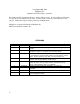
Figure 1.
INTRODUCTION MagTek’s Shift-Out IntelliHead consists of a high-performance multi-channel fully integrated magnetic stripe decoder chip encapsulated within a low-profile magnetic read-head. This innovative, yet low-cost card reading solution offers many important advantages over the conventional lessintegrated approach.
IntelliHead • AGC (Automatic Gain Control) – reads cards from 30% - 200% of ISO 7811 amplitude standard • Simplified firmware – Shift-Out format makes it easier to write controller code • Wide operational temperature range – -40° C to +85° C • Wide range of card swipe speeds – from 3 ips to 100 ips (7 cm/s to 250 cm/s) * See CONFIGURATIONS section below for the definition of 5V unit.
Shift-Out IntelliHead SHIFT-OUT PROTOCOL Refer to MagTek specification 99875337 (99875336 or 99875259 for 5V units) for details of the ShiftOut Protocol. The additional information below is needed for the firmware designer to assign the memory-tracks of the ASIC (A, B, and C) to the physical magnetic head tracks (1, 2, and 3).
IntelliHead TECHNICAL SPECIFICATIONS Technical Specifications are as follows: ELECTRICAL Electrical Details See MagTek Specification 99875337 (99875336 or 99875259 for 5V units) Electrostatic Discharge ± 15kV discharge to head-can with head-can grounded MECHANICAL Dimensions As shown in the Figures at the end of this document Life 1,000,000 Passes ENVIRONMENTAL Operating Environment Temperature Relative Humidity Storage Environment Temperature Relative Humidity 4 -40 oC to +85 oC (-40 oF to +185
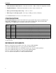
Shift-Out IntelliHead PACKAGING, WIRING, AND MOUNTING Packaging and Pin Assignments Signal and pin assignments for the Shift-Out IntelliHead are shown in Table 1. Table 1. Signal and Pin Assignments – IntelliHead Pin Number 1 2 3 4 5 Description STROBE DATA VDD GND CASE Wiring The Shift-Out IntelliHead Wiring Diagram is shown in Figure 2. The recommended mating connector is Molex 53048-0510. Figure 2. IntelliHead Wiring Mounting The Two-track Shift-Out IntelliHead drawing is shown in Figure 4.
Shift-Out IntelliHead Figure 3.
Shift-Out IntelliHead Figure 4.
Shift-Out IntelliHead Figure 5.
Shift-Out IntelliHead Figure 6.
Shift-Out IntelliHead Figure 7. Three-Track 3V Shift-Out IntelliHead, 4.
Shift-Out IntelliHead Figure 8.
Shift-Out IntelliHead Figure 9.
Shift-Out IntelliHead Figure 10. Three-Track 3V Shift-Out IntelliHead, 5.