
Specifications


MAIN CIRCUIT BREAKER
The main circuit breaker is located on the main control panel. When the breaker is in the OFF “O” position, power is
interrupted between the customer connection lugs and the generator. Once the connections have been made to the
connection lugs and the generator has been started and allowed to reach normal operating temperature, the breaker
may be switched to the ON “I” position.
The main circuit breaker will be tripped, disconnecting power to the connection lugs, if any of the following items
occur while the unit is running:
1. Overload of the generator circuits to the connection lugs.
2. The lug box door covering the customer connection lugs is opened.
3. If the emergency stop switch is activated.
Make sure that any problems that caused the main circuit breaker to trip are corrected before returning the switch to
the ON “I” position.
NOTICE
The main circuit breaker interrupts power to the customer connection lugs only. The customer convenience outlets
have power even if the main circuit breaker is in the OFF “O” position. The auxiliary outlet main circuit breaker,
located next to the main circuit breaker, will disconnect all power to the auxiliary outlet panel.
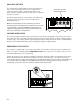
REMOTE START TERMINAL BLOCK
The remote start terminal block is located under the lug box door just below the voltage selector switch. It provides
a connection for installation of a remote start switch which will allow the generator to be started by a remote dry-
contact closure switch.
Before pressing the AUTO button, verify that the contacts on any
remote switch linked to the generator are OPEN. If the contacts on
a remote switch are closed, the generator will crank and start when
AUTO is selected on the controller. Attach the switch leads to the
two unused terminals on the generators remote start block. For
additional information on starting the generator, see the GENERA-
TOR START UP section of this manual.
TRANSFER SWITCH
When the generator is used as a standby power supply, it must be
equipped with a transfer switch which isolates it from the utility’s distribution system. A transfer switch is designed
to transfer electrical loads from the normal power source (utility) to the emergency power source (generator) when
normal voltage falls below a prescribed level. The transfer switch automatically returns the load back to the normal
source when power is restored back to operating levels.
23
FAILURE TO ISOLATE THE GENERATOR FROM THE NORMAL POWER UTILITY CAN CAUSE
POTENTIALLY LETHAL VOLTAGE TO BACKFEED INTO THE UTILITY LINES. THIS MAY RESULT IN
INJURY OR ELECTROCUTION OF UTILITY WORKERS NEARBY. MAKE SURE THAT THE GENERATOR IS
ISOLATED BY A TRANSFER SWITCH FROM ANY LOCAL UTILITY LINES. THIS ALSO APPLIES IF THE
GENERATOR IS BEING USED AS A BACK UP TO SOME OTHER TYPE OF POWER SUPPLY.
DANGER