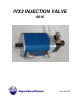
IVX3 INJECTION VALVE 8010 Rev.
IVx3 Injection Valve Manual CORPORATE HEADQUARTERS and MANUFACTURING th 11692 56 Court * Clearwater, FL 33760 * Tel 727-573-2955 * Fax 727-571-3636 TECHNOLOGY CENTER and WEST COAST MANUFACTURING 1862 Ives Ave. * Kent, WA 98032 * Tel 253-854-2660 * Fax 253-854-1666 MVP PLASTECH UK Chilsworthy Beam, Gunnislake, Cornwall, PL18 9AT UK, * Tel:+44 (0) 1822 832621 Fax: +44 (0) 1822 833999 www.mvpind.com Rev.
IVx3 Injection Valve Manual TABLE OF CONTENTS: SECTION: Page TERMS & CONDITIONS OF SALE 4 SAFETY & WARNING INFORMATION 6 INTRODUCTION 15 OVERVIEW 16 IVX3 INJECTION VALVE CONNECTIONS 17 OPERATING PROCEDURES 19 FLUID VALVE REPAIR 20 ACTUATOR REPAIR 26 TESTING 29 PARTS DRAWINGS 34 REVISION INFORMATION 41 Rev.
IVx3 Injection Valve Manual Terms & Conditions of Sale: Customs duties, import and export licenses and certificates, if required, and all local taxes are excluded from this offer. If US state and local taxes are applicable and not included in equipment invoice, such amount may be invoiced later. Delivery dates or shipping schedules are approximate and based upon the most recent information available at the time of order.
IVx3 Injection Valve Manual against the Seller in respect of the goods, the liability of the Seller shall be limited to the value of the goods. Many factors beyond Seller’s control contribute to the success of Buyer’s finished products, such as raw materials used to manufacture the product. Equipment is warranted to perform to specifications detailed in quotation, but Seller is not liable for quality or quantity of finished products produced by Buyer.
IVx3 Injection Valve Manual SAFETY & WARNING INFORMATION: OPERATING YOUR POLYESTER SYSTEM SAFELY 1. Introduction Any tool, if used improperly, can be dangerous. Safety is ultimately the responsibility of those using the tool. In like manner, safe operation of polyester processes is the responsibility of those who use such processes and those who operate the equipment. This manual outlines procedures to be followed in conducting polyester operations safety.
IVx3 Injection Valve Manual Extinguishing Media – Foam, Carbon Dioxide, Dry Chemical, Water Fog. Copies of the above bulletins are available, at a nominal charge from: National Fire Protection Association 470 Atlantic Avenue Boston, MA 02210 Research Report No.11 of the American Insurance Association deal with “Fire, Explosion and Health Hazards of Organic Peroxides”.
IVx3 Injection Valve Manual 2.2 Catalyst (Methyl Ethyl Ketone Peroxide) MEKP is among the more hazardous materials found in commercial channels. The safe handling of the “unstable (reactive)” chemicals presents a definite challenge to the plastics industry.
IVx3 Injection Valve Manual D. Never add MEKP to anything that is hot, since explosive decomposition may result. E. Avoid contact with skin, eyes and clothing. Protective equipment should be worn at all times. During clean-up of spilled MEKP, personal safety equipment, gloves and eye protection must be worn. Fire fighting equipment should be at hand and ready. F. Avoid spillage, which can heat up to the point of self-ignition. G.
IVx3 Injection Valve Manual A. The reaction is unpredictable. Prior use of an HHC solvent without incident (corrosion or explosion) does NOT mean that such use is safe. These solvents can be dangerous alone (as a clean-up or flushing agent) or when used as a component or a coating material. There is no known inhibitor that is effective under all circumstances. Furthermore, the mixing of HHC solvents with other materials or solvents, such as MEKP, alcohol, and toluene, may render the inhibitors ineffective.
IVx3 Injection Valve Manual 2.4 Catalyst Diluents Magnum Venus Plastech spray-up and gel-coat systems currently produced are designed so that catalyst diluents are not required. Magnum Venus Plastech, therefore, recommends that diluents not be used. This avoids the possible contamination which could lead to an explosion due to the handling and mixing of MEKP and diluents.
IVx3 Injection Valve Manual 2.8 Treatment of Chemical Injuries Great care should be used in handling the chemicals (resins, catalyst and solvents) used in polyester systems. Such chemicals should be treated as if they hurt your skin and eyes and as if they are poison to your body. For this reason, Magnum Venus Plastech recommends the use of protective clothing and eye wear in using polyester systems. However, users should be prepared in the event of such an injury. Precautions include: 1.
IVx3 Injection Valve Manual 3.0 Equipment Safety WARNING Magnum Venus Plastech suggest that personal safety equipment such as EYE GOGGLES, GLOVES, EAR PROTECTION, and RESPIRATORS be worn when servicing or operating this equipment. Ear protection should be worn when operating a fiberglass chopper to protect against hearing loss since noise levels can be as high as 116 dB (decibels).
IVx3 Injection Valve Manual 3.2 Grounding Grounding an object means providing an adequate path for the flow of the electrical charge from the object to the ground. An adequate path is one that permits charge to flow from the object fast enough that it will not accumulate to the extent that a spark can be formed. It is not possible to define exactly what will be an adequate path under all conditions since it depends on many variables.
IVx3 Injection Valve Manual Introduction: The IVX3 was designed specifically as part of the Flex Molding process to streamline the infusion process by reducing the number of valves needed. The IVX3 is a pneumatically activated three position valve – Inject, Off and Purge. The IVX3 is compatible with the MVP universal mold insert and suitable for use in other closed mold applications such as RTM Light.
IVx3 Injection Valve Manual Overview: Purge signal port Inject signal port Purge Outlet Hose Resin / Purge Input Hose with QD connector Fluid Valve assembly Universal Insert / Injection Port IVX3 Valve Mode Overview: OFF Mode – this is the default mode – the injection, purge and input ports are blocked. Closed - no fluid can move through the valve.
IVx3 Injection Valve Manual Connections: Stand-Alone Injection Valve – When used as a stand-alone injection valve it, can be remotely controlled. To put the IVX3 into Injection mode send a constant 6 bar (90psi) air signal to the Injection Signal port. Remove the air signal and the valve will return to the Off mode. To put the IVX3 into Purge mode send a constant 6 bar (90psi) air signal to the Purge signal port. Again remove the air signal and the valve will return to the Off mode.
IVx3 Injection Valve Manual IVX3 with PPVS-INFUSION Valve – connecting the IVX3 Injection valve to the PPVSINFUSION will allow for automatic Open / Close control of the IVX3 valve based on the vacuum level. Connect the output signal of the PPVS to the Inject Signal port on the IVX3 valve. Connect the Purge Signal port to a purge valve or flush signal.
IVx3 Injection Valve Manual Operating Procedures: NOTE: Apply release agent to the internal 10mm bore of the valve (inside the nose) when the valve is actuated in the inject position (shaft up-most) to prevent the seal sticking up. Operating Procedures using PPVS: 1. Put the IVX3 Valve in the Off mode (CLOSED). 2. Set MPG pressure and pump pressure. Caution: Do not exceed the Pressure Rating of the injection hose for the MPG or Pump pressure.
IVx3 Injection Valve Manual Fluid Valve Repair: NOTE: It is important to have the correct parts drawing for the item you are working on. This will assist in identifying the correct part numbers for the assembly being rebuilt. IVX3 Spares Kit (8011) IVX3 Tool Kit (8012) Flat Tip Screw Driver for 7057 Flat Tip Screw Driver for 7055 Red Grease (6706-2-1 1oz) The IVX3 Tool Kit (8012) comprises of two specialized tools, IVX3 Tool A and IVX3 Tool B.
IVx3 Injection Valve Manual 4. Re-attach the Lower Valve Body (6986) to the Upper Valve Body (6985) using one of the Machine Screws (7057). Position the Lower Valve Body as shown below and tighten the screw. 5. Apply air to the actuator to move the valve to the Purge position and fully expose the seal as shown below. 6. Use IVX3 Tool A or B on the flats of the Seal Upper Insert (6978) to stop it turning as you unscrew the Slotted Screw (7055) from the end of the Lower Insert (6979). 7.
IVx3 Injection Valve Manual Note: It is important to follow the following steps carefully to ensure the seal is not damaged during the installation process. 11. Apply Red Grease (6706-2-1 1oz) to the Seal – Hard Wearing (7052) to ensure that it is well lubricated. 12. Put the Valve into the Off mode by removing the air signal from the upper port. This will pull the new seal partially back into the Upper Valve Body (6985). 13.
IVx3 Injection Valve Manual Disassembly: 1. Remove and replace the two O-rings (3265) on the Nose of the Lower Valve Body (6986). Apply a light coat of the Lubrication to the two O-rings. 2. Supply air to the actuator to move the valve to the Inject position. 3. Remove the two (2) Machine Screws (7057) from the bottom of the valve. 4. Carefully remove the Lower Valve Body (6986) from the Upper Valve Body (6985). 5.
IVx3 Injection Valve Manual 12. Using the IVX3 Tools A and B remove the Seal Upper Insert (6978) from the end of the Lower Shaft (6977) of the actuator. 13. Slide the Valve Bush (7052) off the end of the Lower Shaft (6977). 14. Check all parts for wear and replace any damage or worn items. Assembly: 1. Replace all old or damaged O-rings with new ones from the Spares Kit (8011). Apply a coat of lubrication to the O-rings using Red Grease (6706-2-1 1oz). 2.
IVx3 Injection Valve Manual 8. With a new O-ring (6988) installed on the Seal Lower Insert (6979), press this into the end of new Seal – Hard Wearing (7051). 9. Apply a drop of removable thread lock compound to the end of the Slotted Screw (7055) and thread it into the end of the Seal Upper Insert (6979). Use IVX3 Tool A or B on the flats of the Seal Upper Insert to stop it turning as you tighten the Slotted Screw.
IVx3 Injection Valve Manual Actuator Repair: To repair the Actuator Assembly the Fluid Valve must first be removed. IVX3 Spares Kit (8011) IVX3 Tool Kit (8012) Flat Tip Screw Driver for 7056 SUPERLUBE or MOLYKOTE 111 grease Remove the Fluid Valve: Follow the instructions given in Chapter 5 to remove the fluid valve. Actuator Disassembly: 1. Carefully remove the four (4) Machine Screws (7056) from the top of the Cylinder Lid (6980).
IVx3 Injection Valve Manual 9. Pull the Actuator Piston Assembly, shown below, from the Int Cylinder Body (6974). Int Cylinder Cap Int Cylinder Body IVX3 Tool A Lower Spring Actuator Piston Assembly IVX3 Tool B 10. Remove the Lower Spring (7040) from the INT Cylinder Body. 11. Replace the two Lip Seals (5836) on the Actuator Piston Assembly and lightly coat with MOLYKOTE 111 or SUPERLUBE grease. 12.
IVx3 Injection Valve Manual 4. Put the Upper Spring (7041) into the Actuator Cylinder (6981) on top of the Int Cylinder Cap (6975). 5. Install the Cylinder Lid (6980) onto the Actuator Cylinder (6981) over the Upper Shaft (6976) – the Upper Shaft will show in the Top Bush (6982) in the Cylinder Lid. 6.
IVx3 Injection Valve Manual Valve Testing: After an IVX3 has been serviced, MVP recommends that it should be fully tested before it is used in production. The following items are required to test the valve: 8018 – IVX3 SERVICE MODULE (shown below) Soapy water We recommend that during a service the actuator assembly is first tested prior to fitting the fluid section. NOTE: See the IVX3 Service Module manual for more detailed instructions on its use for testing the IVX3. IVX3 SERVICE MODULE (8018) Rev.
IVx3 Injection Valve Manual Actuator Testing – Fluid section removed: 1. Connect the Purge output on the top of the Service Module to the purge signal port on the IVX3. 2. Connect the Inject output on the top of the Service Module to the inject signal port on the IVX3. 3. Operate the switch on the Service Module and put the valve in the Inject position.
IVx3 Injection Valve Manual Actuator Testing – Fluid Section Fitted: Follow the steps listed for testing the actuator with the fluid section removed, but when testing for air leaks at the Bottom Bush (6983), apply soapy water to the Isolation Channel shown in the image below. Isolation Channel Fluid Section Testing – Vacuum Integrity: 1. Ensure the Resin inlet and Purge outlet hoses are exhausted and not connected to any equipment. 2.
IVx3 Injection Valve Manual 7. Once a suitable vacuum level is reached, close the isolation valve on the Service Module to isolate the vacuum source from the IVX3’s injection port. Ideally the level on the vacuum gauge should remain stationary and the vacuum should be maintained. 8. Actuate the IVX3 to the Purge position; the vacuum level should decrease slightly as the seal moves. In this position the vacuum level should again be maintained.
IVx3 Injection Valve Manual 7. Apply soapy water to the seal in the Lower Valve Body (6986) and look for bubbling that would imply a leak (do not point the resin outlet directly at yourself). It is acceptable to have a small leak here. 8. Operate the IVX3 to the Purge position; the indicator/gauge should now show pressure. Once again apply soapy water to the seal and check for leaks. There should not be any leaks here if the valve is in good condition. 9.
IVx3 Injection Valve Manual Parts Drawings: 8010 ASSY-0473 ASSY-0483 IVX3 Injection Valve Assembly IVX3 Actuator Assembly IVX3 Fluid Valve Only Assembly Rev.
IVx3 Injection Valve Manual Rev.
IVx3 Injection Valve Manual Rev.
IVx3 Injection Valve Manual Rev.
IVx3 Injection Valve Manual Rev.
IVx3 Injection Valve Manual Rev.
IVx3 Injection Valve Manual Rev.
IVx3 Injection Valve Manual Revision Information: Revision: Description: Rev. 12/2011 Created IVX3 Injection Valve Manual. Rev. 03/2012 Maintenance procedures revised, chapter on testing added and drawing updated. The Terms & Conditions Section was also added. Updated the manual format. Rev.
IVx3 Injection Valve Manual MAGNUM VENUS PLASTECH CORPORATE HEADQUARTERS and MANUFACTURING th 11692 56 Court * Clearwater, FL 33760 * Tel 727-573-2955 * Fax 727-571-3636 TECHNOLOGY CENTER and WEST COAST MANUFACTURING 1862 Ives Ave. * Kent, WA 98032 * Tel 253-854-2660 * Fax 253-854-1666 MAGNUM VENUS PLASTECH LTD Chilsworthy Beam, Gunnislake, Cornwall, PL18 9AT UK, * Tel:+44 (0) 1822 832621 Fax: +44 (0) 1822 833999 www.mvpind.com Rev.