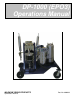
DP-1000 (EPO3) Operations Manual MAGNUM VENUS PRODUCTS Operations Manual Part No.
DISCLAIMER: The information in this document is presented in good faith and is based on the best available data. Because chemistry of materials, operation al demands, and other conditions vary from one plant to another, and from one time to another; Magnum Venus Products cannot give specific instructions for adjusting and operating your equipment. We do give guidelines and urge customers to perform the operations and products tests described in this manual and all other pertinent documents.
Table of Contents DP-1000 (EPO-3) Operations Manual Safety Labels INTRODUCTION The EPO3 Dual Pump Meter/ Mix Unit INSTALL THE NEW UNIT Uncrate Unit Tool List Install Material Containers Remove Unit Metal Cover Turn Front Panel Controls Off Front Panel Controls Unit Side Panels Install Electrical Wire Install Hoses Attach Air Lines PRIME THE UNIT Special Conditions: Sensitive Materials Check Hose Fittings Fill Solvent Tank Disassemble Gun-Head Pressurize Solvent Tank Flush Gun Recheck Hoses Fittings Set Pu
Recheck Pressure Correct Pressure Drift Change To Operating Mode Test Spray Patterns THE ACCUMULATORS Remove Fluid and Air Pressure Charge Accumulators with Charging Pump Test For Proper Mix RESIN INJECTION Requirements Testing RTM Mix SHUTDOWN PROCEDURES Short-Term Procedure Long-Term Procedure WEEKLY MAINTENANCE Maintenance Procedures APPENDIX A: OPTIONAL EQUIPMENT Air Assist Nozzle Chopper Digital Resin Meter Nitrogen Accumulator Charging System APPENDIX B: SPRAY NOZZLE LIST
DANGER: Only Qualified Electricians Should Install Electrical System! WARNING: Air Pressure Should Not Exceed 120 psi! WARNING: Wear Eye Protection When Working With Solvent! WARNING: Do Not Disable Pressure Relief Valve on Solvent Tank! WARNING: If Pump Runs Rapidly Shut Off Main Pressure Immediately! DANGER: Nitrogen Bottles Should Be chained Securely! WARNING: Never Allow Pump Pressure to Exceed 1200 psi Or Heaters May Rupture! DANGER: Never Operate Unit Without Accumulator Safety Cover! WARNING: Never R
INTRODUCTION The EP03 Dual Pump Meter/ Mix Unit The EPO3 unit is a medium –to high-volume metering and mixing system capable of metering two components at rations from 1:1 through 8:1, depending upon pump selection and pump settings. The unit is capable of supplying a smooth, continuous flow of fully-mixed, reactive thermosetting materials. A static mixing element used at the gun produces full mixing of most medium viscosity epoxies, polyesters, and other thermosetting resins.
Larger quantities require installation of material containers with material heating supplied for viscosity control. If your material is under 1,000 centipoise at room temperature, you can operate without bulk material heating.
CHAPTER 2 INSTALL THE UNIT Uncrate Unit Uncrate the unit and set on level floor surface at least 3 feet from the nearest wall to allow easy access. Tool List When preparing the EPO3 for use, it is important to have all of the tools, spare parts, and the supplies available before beginning operation. The following tools (not shipped with the unit) must be available when using the EPO3. Protective gloves approved for use with all materials to be handled.
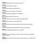
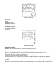
(Figure 1. Front Panel Controls) Turn off all front panel switches. Turn all regulators to “0” (zero) or fully counterclockwise. Turn off MAIN PRESSURE to unit. Check that heater indicator on the front panel is OFF (do not activate heaters). Front Panel Controls Each control on the front panel is described in the following: The HEAT indicator, on the left and right sides of the control panel, shows when the heaters are ON or OFF. When the HEAT is on the lens turns green.
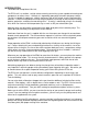
(Figure 2. Inlet Panel) Outlet Panel RESIN HEATER RESIN RESIN RETURN HARDENER HEATER HARDENER HARDENER RETURN AIR SUPPLY AIR SIGNAL RETURN SOLVENT (Figure 3. Outlet Panel) Install Electrical Wire DANGER: Only Qualified Electricians Should Install Electrical System! Install electrical wire (220 single phase, 25 amp) through manifold panel at lower side of machine (see Figure 4). If flammable materials are to be processed, explosion –proof wiring must be used.
(Figure 4. Power Supply Connection) Install gun hoses at OUTLET PANEL with black supply hoses and recirculation hoses attached at left side of right panel according to fitting sizes (see Figure 3). Be extremely careful to attach the resin and hardener recirculation hoses to the proper fitting or material cross-over can occur. Use colored tape to color-code hoses according to material. Place pickup wands into barrels or attach green hoses to bottom fitting on bulk containers.
CHAPTER 3 PRIME THE UNIT Special Conditions: Sensitive Materials If your materials are extremely sensitive to moisture or contamination, it is advisable to first prime both pumps with a compatible solvent to remove any oil residue from the unit. The solvent containers should then be disposed of properly. Use approved containers for all flushing and priming procedures. Check hose Fittings Check all hose fittings on the unit to be sure they are tight.
Disassemble Gun-Head Remove mixing tube or spray nozzle from gun-head (see Figure 8). Remove turbulent mixer (if used) and front resin gun plug from gun to allow proper solvent flushing (see Figure 9). Remove check balls and valve springs and clean with solvent. Inspect the check ball seats for hardened material. If you find any, clean the seat with solvent.
(Figure 10. Loosen Slave Arm Bolts) (Figure 11. Adjust Slave Arm Screw) Check that all ball valves levers located on INLET PANEL are in the open position (parallel with the hoses). The location of the ball valves is described in the following list: One on each pump (2). One on the RESIN RETURN HOSE. One on the HARDENER RETURN HOSE. Recirculate Material Material must be recirculated past the gun-head through a return fitting to prime the unit. No material will exit the gun.
CHAPTER 4 PRIME THE UNIT (contd.) Find Mixing Ratio Consult your material data sheet to find proper mixing ratio. Set variable-stroke length pump to proper ratio number as stamped on top edge of slave-arm (see Figure 12) Choose Pump Size To select the correct pump size, perform the following steps: If the material requires greater than a 4:1 ratio, use a smaller diameter variable-stroke fluid pump (1 ¼”).
Choose an arbitrary length of time, such as thirty seconds and remove both pre-weighed containers from the stream after the length of time you have chosen. If you are checking ratios by volume it is not necessary to pre-weigh containers. If, after checking the ratios, you have an inaccurate ratio, loosen the slave-arm and adjust slightly before rechecking the ratios. Mark reference points on the slave arm with a pencil after each adjustment.
CHAPTER 5 PRESSURE AND ADJUSTMENT Select Injectors Four injectors are supplied with each unit and must be selected for each application according to back pressures developed by the variable-ratio pump (#1 is the largest, #4 is the smallest). Typically the #3 injector should be used for 3:1 ratio materials and #4 injector should be used for 4:1 ratio materials, etc. High ratio materials require less flow through the injector.
(Figure 14. Assemble Turbulent Mixer) (Figure 15. Insert Injector) Recheck Pressure Set MAIN PRESSURE to estimated operating pressure of the unit. Start at 30psi for RTM and 50 psi for spraying. Pull gun trigger and operate until pressure stabilizes. Check pressure gauges mounted on the front panel. If one gauge reads more than 200psi higher pressure than the other, increase resin heater on that side of the machine by turning block heat knob to an increased value position.
It is also possible to help compensate for this effect by proper selection of accumulator sizes on the “PUMP H.” A hardener pump operating at an 8:1 ratio may be equipped with an accumulator having approximately 1/8 the volume of the resin accumulator (4:1 at ¼, etc.). When using accumulators at this reduced volume, the charging and testing procedure must be performed correctly. Properly matched accumulators may prevent the necessity of pre-pressurizing the “PUMP H” by restricting recirculation.
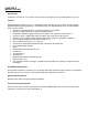
If the pressure is not adequate to form a well-defined fan pattern, increase the MAIN PRESSURE until there is just enough pressure to form a proper fan pattern. Described in the following are possible problems and their solutions with fan pattern: One Narrow Stream: The MAIN PRESSURE is too low for the material you are using (see Figure 16 on previous page). Solution: Increase the MAIN PRESSURE. Increase the material’s temperature. Use a smaller nozzle size.
(Figure 19. Almost Normal Spray Pattern) (Figure 20. Normal Spray Pattern) Pattern Too Wide: Heavy misting is seen and smelled, and there is significant overspray (material laid down beyond the main pattern). The heavy frothing does not disappear within 2 minutes (see Figure 21) Note: This is the most common problem in running the unit. Solution F: Reduce the MAIN PRESSURE until the fan pattern fails, then increase the pressure until the proper fan pattern returns.
CHAPTER 6 THE ACCUMULATORS If Removal of the variable-stroke accumulator safety cover is necessary, place the rubber sleeve (1) over the accumulator and then install the safety shield (2) (see Figure 22) Remove Fluid and Air Pressure WARNING: Never Remove Accumulator Safety Cover Before All Air And Fluid Pressure Has Been Relieved! Remove all fluid pressures from the unit by using the following procedure: Turn “ON” the MAIN PRESSURE switch. Turn “OFF” the MAIN PRESSURE regulator completely.
Attach red line-air hose from manifold of unit (located on the pump pivot support bracket) to quickdisconnect. (Figure 24. Extend Charging Pump Handle) (Figure 25. Attach Charging Hose) Be sure recirculation valves (located on the INLET PANEL) are open so fluid can exit accumulator during charging. The gauge on the charging pump should read line pressure. Operate charging pump by placing handle against your chest and pressing pump against the handle.
If pulsations occur, repeat entire accumulator charging procedure at ½ the previously tested charge and then increase the charge at 100 psi increments until pulsation disappears. If adjustment of charging pressures does not remove pulsations during the reversal of the pump, it may be necessary to select a different accumulator size for the variable-stroke pump. Test For Proper Mix To test spray –up pattern, spry strip of material on a piece of paper with steady gun movement across the paper.
CHAPTER 7 RESIN INJECTION Requirements The RTM (Resin Transfer Molding) is identical to the spraying process with the exception of the lower operating pressures. It may be possible to operate MAIN PRESSURE at the same pressure as recirculation pressure, eliminating some procedures necessary for balancing startup pressures. Resin injection also requires the use of a static-mixing tube attached to the standard gun-head to achieve proper blending of tube components.
CHAPTER 8 SHUT DOWN PROCEDURES Short-Term Procedure DANGER: Never Leave Flammable Solvents Under Pressure Overnight! When shutting down unit for more than 10 minutes but less than two weeks, use the following procedure: Flush the gun-head with solvent by pushing the trigger forward. Disassemble the gun-head and clean with the proper solvent (see Figure 26). Flush the gun-head again with solvent. Remove air pressure at MAIN PRESSURE gauge. Turn OFF power to the unit.
(Figure 27. Clean Filters) (Figure 28. High Pressure Relief Valve) (Figure 29.
CHAPTER 9 WEEKLY MAINTENANCE Maintenance Procedures DANGER: Never Remove Accumulator Safety cover When Pressure Is Present in The Variable-Stroke Pump Accumulator! Preferably Friday evening or the last workday of the week, perform the following maintenance steps: Clean the high pressure relief valve system and accumulators. Clean fluid filter with proper solvent. Bleed all water traps, compressor system and water trap located on air manifold (on pump pivot support bracket) (see Figure 30).
(Figure 32. Disassemble Accumulators) (Figure 34. Clean Filters) (Figure 33. High Pressure Relief Valve). (Figure 35. Fill Pump Shaft Oil Cups) Thoroughly wash all components with the proper solvent. Flush solvent through the high-pressure relief valve hose by using the special gun adaptor fitting supplied with the unit. (See Figure 36) During this procedure, the pump filters should also be thoroughly cleaned.
APPENDIX A OPTIONAL EQUIPMENT Air-Assist Nozzle The optional Air-Assist Nozzle can be provided with a pressure gauge and regulator on the front panel o the unit. This nozzle includes a small mixing element which can be supplemented by inserting a standard turbulent mixer into the front of the gun-head. An air line goes to the air-assist nozzle. The nozzles available for the air-assist are different from the standard MVP H.I.S. nozzles (see Appendix B for list).
(Figure 37. Nitrogen Charging System) Remove the valve body cap on the top of both accumulators. Note: Do not switch valve body caps between accumulators. The hardener pump’s cap must be returned to hardener pump to avoid contamination. Clean the end of an allen wrench or flat-end rod and insert in the top of the accumulator valve, press down until all air escapes. Attach nitrogen lines to the tops of the accumulators. Always use the same hose on the same accumulator to avoid contamination.
APPENDIX B SPRAY NOZZLE LIST Air-Assisted Spray Nozzle List Use these lists to choose the best output, pattern width, and back pressure for your application. Orifice Size Part Number Air Cap Used 30423 30427 30431 30435 30443 30523 30535 30543 30623 30627 30631 08228 08229 08229 08229 08229 08228 08229 08229 08228 08229 08229 Tungsten Carbide Spray Nozzle List Orifice Size Fan Angle (degrees) Part Number 0.026 0.036 0.043 0.052 0.062 0.011 0.013 0.015 0.018 0.021 0.023 0.026 0.031 0.036 0.043 0.
0.011 0.013 0.015 0.018 0.021 0.023 0.026 0.031 0.036 0.043 0.062 0.072 65 65 65 65 65 65 65 65 65 65 65 65 650017 C 650025 C 650033 C 650050 C 650067 C 650080 C 6501 C 65015 C 6502 C 6503 C 6506 C 6508 C Note: There are other fan angles available, but this list comprises our normal stock. 0.06 0.09 0.12 0.18 0.24 0.28 0.35 0.53 0.71 1.40 2.10 2.
Corporate Headquarters/Manufacturing th 5148 113 Ave. Clearwater, FL 33760 USA Ph: (727) 573-2955 Fax: (727) 571-3636 Manufacturing/Sales 1862 Ives Ave. Kent, WA 98032 USA Ph: (253) 854-2660 Fax: (253) 854-1666 E-mail: info@mvpind.com · Web: www.mvpind.