APS FIT Chop System FIT-C-APS-3 Maintenance & Repair MAGNUM VENUS PRODUCTS Maintenance & Repair Manual Part No. FIT-C-APS-3 Revision 05.14.
APS FIT Chop System Maintenance & Repair Manual Corporate HQ & Mfg. Phone: (727) 573-2955 Fax: (727) 571-3636 MVP Technology Center Phone: (253) 854-2660 (800) 448-6035 Fax: (253) 854-1666 E-mail: info@mvpind.com · Web: www.mvpind.
Table of Contents APS FIT Chop System Maintenance & Repair Manual C H A P T E R 1 - BASIC TROUBLE SHOOTING GUIDES HPC-1000 Slave Pump Fluid Sections Choppers C H A P T E R 2 - RC-1000 & RC-1101-1 ROVING CUTTER INSTRUCTIONS C H A P T E R 3 - ASSEMBLY PROCEDURE FOR RC-1101-1 AIR MOTOR C H A P T E R 4 - CAUTIONS & WARNINGS C H A P T E R 5 - PARTS DRAWINGS
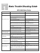
Chapter 1 Basic Trouble Shooting Guide Problem No catalyst coming from gun. HPC-2000 Slave Pump Possible Cause(s) Recommended Solution Ball valve open on catalyst manifold (if applicable). Be sure ball valve is fully closed. Air is drawn into catalyst siphon assembly Replace inlet nipple Cracked or deteriorated (pin holes) inlet nipple at bottom of slave pump. Catalyst spitting from gun. Worn or cut O-ring in inlet nipple. Replace O-ring in inlet nipple. Improper seal around siphon hose.
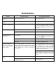
Fluid Sections Problem Possible Cause(s) Recommended Solution Fast downstroke (winking of Debris on lower ball seat. pattern). Disassemble and clean. Fast upstroke (winking of pattern). Debris on upper ball seat. Disassemble and clean. Partial dive on downstroke. Air siphoning. Check for loose fittings from bottom of pump to the end of the siphon assembly. Inspect for kinks, cuts, loose fittings, etc. and correct as necessary. Pump stroke “chatter”.
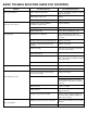
BASIC TROUBLE SHOOTING GUIDE FOR CHOPPERS Problem Cutter not shutting off. Cutter does not come on. Glass binds up. Improper chop length. Cutter running too slow. Possible Cause(s) Recommended Solution Stuck chopper poppet valve Replace and lubricate O-ring on chopper poppet valve in gun. Worn poppet valve seat. Replace Broken poppet valve spring.
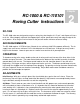
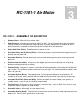
Chapter RC-1000 & RC-110101 Roving Cutter Instructions 2 RC-1000 The RC-1000 cutter was designed to cut glass roving into short lengths of 1/2” to 4”, and dispense it into a resin fan. When properly adjusted, the chopped glass will be spread out evenly from edge to edge of the resin pattern. Also, the glass/resin mixture on the part will need a minimum amount of rolling. AIR REQUIREMENTS The RC-1000 requires 15 CFM of clean, filtered air at a minimum of 90 PSI to operate efficiently.
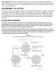
Cutter Adjustment: The glass should enter the resin fan as soon as possible without excessive glass fallout. Normally, if the glass enters the resin when the glass pattern and resin pattern are about the same width it will give the best resluts. This is achieved by centering the glass pattern by moving the cutter left or right -- forward or backward. DISASSEMBLY OF CUTTER Remove the air motor and manifold assembly by first removing the snap ring and anvil sleeve.
Chapter RC-1101-1 Air Motor 3 RC-1101-1 ASSEMBLY OF AIR MOTOR 1. Remove Burrs: With fine file or emery cloth. 2. End Clearance: Average end clearance .0015” to .002”. To get end clearance take micrometer reading of body minust micrometer readin gof rotor assembly, add gaskets (if needed) to get required clearance, assemble air motor with gaskets on both drive and dead end. 3. Select End Plate (Drive): End plate with no threads in hub. 4.
13. Select End Plate (Dead): End plate with threads in hub. When assembled, kidney ports in end plates must be on intake side. 14. Assemble End Plate (Dead): Position end plate over shaft, place on body, assemble screws, snug, loosen one turn. 15. Assemble Bearing: Place bearing on shaft, using bearing pusher, position bearing in end plate. 16. Check Movement of End Plate: End plate must move back and forth. If no movement, top clearance is not in center-reset top clearance.
Chapter Cautions and Warnings 4 AIRLESS EQUIPMENT SAFETY Injection Hazard • DO NOT POINT THE GUN AT ANY PERSON • NEVER LOOK AT THE GUN FROM THE FRONT (NOZZLE END) • NEVER trigger an airless gun while it is aimed at a person. The hydraulic pressure may inject fluid into the flesh, causing injury or death. If the fluid penetrates the skill it WILL cause serious injury. Clothing, such as gloves will NOT provide protection. The system is capable of fluid pressure high enough to cause a LETHAL INJECTION.
Correct packing or valve seal leaks IMMEDIATELY. Frequently check the condition of all pressurized components, especailly fluid lines. Replace worn lines and parts before they fail. If nozzle clogging occurs frequently, use a fluid filter with proper mesh size. PUMPING SYSTEM SAFETY INSTRUCTIONS Use MVP replacement parts to assure compatible pressure rating. Read ALL warning and safety instructions carefully before operation of this unit. Heed all warnings.
Filtered and oiled air will allow the pump to operate more efficiently and yield a longer life to operating parts and mechanisms. Keep oiler supplied with MVP Pump Motor Oil. A filter capable of filtering particles larger than 50 microns should be used with an oiler. Maintenance: If the pump is to be inoperative for a lengthy period of time (even for a few hours) disconnect air and relieve all pressure from system. Periodically flush pump with a solvent that is compatible with the material being pumped.
Chapter 5 Parts Drawings
Corporate HQ & Mfg. Phone: (727) 573-2955 Fax: (727) 571-3636 MVP Technology Center Phone: (253) 854-2660 (800) 448-6035 Fax: (253) 854-1666 E-mail: info@mvpind.com · Web: www.mvpind.