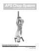
APS Chop System E-FIT-F-CMB-APS-6 Maintenance & Repair MAGNUM VENUS PRODUCTS Maintenance & Repair Manual Part No. E-FIT-F-CMB-APS-6 Revision 05.14.
APS Chop System Maintenance & Repair Manual Corporate HQ & Mfg. Phone: (727) 573-2955 Fax: (727) 571-3636 MVP Technology Center Phone: (253) 854-2660 (800) 448-6035 Fax: (253) 854-1666 E-mail: info@mvpind.com · Web: www.mvpind.
Table of Contents APS Chop System Maintenance & Repair Manual C H A P T E R 1 - START-UP PROCEDURES Inspection of Unit Preparation and Priming of “New” System Preparation and Priming of Previously Used System Air Pressures and Testing of Spray Pattern C H A P T E R 2 - SHUT-DOWN PROCEDURES C H A P T E R 3 - ATC GUN INSTRUCTIONS C H A P T E R 4 - RC-1000 & RC-1101-1 ROVING CUTTER INSTRUCTIONS C H A P T E R 5 - NOZZLE INFORMATION C H A P T E R Chop System Fluid Section 6 - BASIC TROUBLE SHOOTING GUID
Chapter 1 Start-Up Procedures INSPECTION & MAINTENANCE OF UNIT 1. Check solvent cup to be sure it is 1/3 full. 2. Check catalyst and material levels. 3. Inspect material spray tip and O-ring and replace if necessary. 4. Inspect catalyst tip assembly and replace O-rings (if applicable). 5. Inspect tip pin O-rings on front of gun head and replace if nicked or worn. 6. Assemble catalyst tip and material tip onto gun. 7. Lubricate threads on retaining ring and assemble onto gun. 8.
PREPARATION AND PRIMING OF “NEW” SYSTEM 1. Be sure all air regulators are turned completely to the left, shutting off air to the components. 2. Slowly open main air. 3. Prime empty catalyst line: · Disengage catalyst pump · Open ball valve on catalyst manifold (if applicable) · Eliminate air pockets by manually hand pumping the catalyst 5-10 short strokes (2-3 in.). After eliminating air pockets, and while continuing to hand pump, close ball valve on catalyst manifold.
AIR PRESSURES 1. Air requirement recommendations: · A minimum of 100 psi on main air. · 20 - 30 CFM for chopper systems 2. Material pump: 30 - 50 psi 3. Catalyst Atomizing Air: Catalyst atomizing air should be balanced generally between a range of 15 25 psi. It should be low enough to reduce catalyst over-spray and high enough to atomize catalyst efficiently. This allows user to attain and operate under optimum efficiency.
Chapter Shut-Down Procedures 1. Trigger gun until pump shaft is in the full down position (at bottom of stroke position). 2. Engage gun trigger lock. 3. Relieving pressures: 2 · Close main air valve to system. · Purge excess air from system by relieving air from the bottom of the air filter or water trap. · Catalyst pressure: “Dump” or relieve catalyst pressure at catalyst manifold (if applicable) by opening catalyst ball valve. Pressure will immediately be relieved.
Chapter 3 ATC Gun Instructions FEATURES OF THE AT SERIES ACTUATED GUNS There is basically one adjustment on the gun. This is the air refinement adjustment. All adjustments of needles, etc. have been taken out of ht egun. The AT series guns are “air trigger” guns. Air is moved into two chambers in which are located two pistons. The air moves the pistons forward or backward depending on the position of the trigger, e.g. on or off. These air pistons in turn are attached to the needle assemblies.
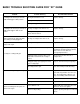
BASIC TROUBLE SHOOTING GUIDE FOR “AT” GUNS Problem Air leaking from exhaust port on back handle while trigger is OFF position. Possible Cause(s) O-ring material worn or cut. Recommended Solution Replace O-rings. O-rings on catalyst piston worn or cut. O-rings on trigger valve worn or cut. Air leaking from exhaust port on back of handle while trigger in OFF or ON position. O-rings on trigger valve worn or cut. Replace O-rings.
Chapter 4 RC-1000 & RC-110101 Roving Cutter Instructions RC-1000 The RC-1000 cutter was designed to cut glass roving into short lengths of 1/2” to 4”, and dispense it into a resin fan. When properly adjusted, the chopped glass will be spread out evenly from edge to edge of the resin pattern. Also, the glass/resin mixture on the part will need a minimum amount of rolling. AIR REQUIREMENTS The RC-1000 requires 15 CFM of clean, filtered air at a minimum of 90 PSI to operate efficiently.
Cutter Adjustment: The glass should enter the resin fan as soon as possible without excessive glass fallout. Normally, if the glass enters the resin when the glass pattern and resin pattern are about the same width it will give the best resluts. This is achieved by centering the glass pattern by moving the cutter left or right -- forward or backward. DISASSEMBLY OF CUTTER Remove the air motor and manifold assembly by first removing the snap ring and anvil sleeve.
RC-1101-1 ASSEMBLY OF AIR MOTOR 1. Remove Burrs: With fine file or emery cloth. 2. End Clearance: Average end clearance .0015” to .002”. To get end clearance take micrometer reading of body minust micrometer readin gof rotor assembly, add gaskets (if needed) to get required clearance, assemble air motor with gaskets on both drive and dead end. 3. Select End Plate (Drive): End plate with no threads in hub. 4.
BASIC TROUBLE SHOOTING GUIDE FOR CHOPPERS Problem Cutter not shutting off. Cutter does not come on. Glass binds up. Improper chop length. Cutter running too slow. Possible Cause(s) Recommended Solution Stuck chopper poppet valve Replace and lubricate O-ring on chopper poppet valve in gun. Worn poppet valve seat. Replace Broken poppet valve spring.
Chapter 5 Tungsten Carbide Spray Nozzle Information TUNGSTEN CARBIDE SPRAY NOZZLE SELECTION X - XXX For MG-3000 use . . . . . . . M2-----For LW-2500 use . . . . . . . . LW-----For ATG-3500 use . . . . . . . . .ATG-----For ATC-4000 use . . . . . . . . . ATC-----For MIX-1000 use . . . . . . . . . ALCEL-----For MIX-6000-C & MIX-5500-G use . . . . .
MAINTENANCE INSTRUCTIONS FOR FLAT SPRAY TUNGSTEN CARBIDE TIPS Your carbide tip has a precisely machined orifice and with proper care will give a long useful life. Remember, the orifice tip is brittle . . . it should never be dropped . . . or probed with a sharp metal object. The following steps should be taken to keep the tip clean and ready for use: STEP 1 Immediately after spraying submerge spray tip in solvent until film or coating dissolves completely. STEP 2 Blow out tip with compressed air.
Chapter 6 Basic Trouble Shooting Guide Problem No catalyst coming from gun. HPC-2000 Slave Pump Possible Cause(s) Recommended Solution Ball valve open on catalyst manifold (if applicable). Be sure ball valve is fully closed. Air is drawn into catalyst siphon assembly Replace inlet nipple Cracked or deteriorated (pin holes) inlet nipple at bottom of slave pump. Catalyst spitting from gun. Worn or cut O-ring in inlet nipple. Replace O-ring in inlet nipple. Improper seal around siphon hose.
Fluid Sections Problem Possible Cause(s) Recommended Solution Fast downstroke (winking of Debris on lower ball seat. pattern). Disassemble and clean. Fast upstroke (winking of pattern). Debris on upper ball seat. Disassemble and clean. Partial dive on downstroke. Air siphoning. Check for loose fittings from bottom of pump to the end of the siphon assembly. Inspect for kinks, cuts, loose fittings, etc. and correct as necessary. Pump stroke “chatter”.
Chapter 7 Magnum Air Motor DISASSEMBLY 1. 2. 3. 4. 5. 6. 7. 8. 9. 10. 11. 12. 13. 14. 15. 16. 17. 18. 19. 20. 21. Place motor in upstroke position. This can be accomplished by pushing rod toward top of the air motor. Remove four screws from deflector. Remove deflector. Remove 6 screws from air motor cap. Remove air motor cap and gasket. Loosen 4 screws, which hold valve plate and valve guide, until valve guide can be removed by pulling upward.
22. 23. 24. 25. 26. 27. 28. 29. 30. 31. 32. Remove O-ring from head assembly. Remove 4 screws from gland permiting gland to be removed from head assembly. Remove O-rings from gland. Remove tube assembly from base. Remove two O-rings from tube. Remove cylinder from base. Usually during this step the piston and rod assembly will remain in cylinder. From base assembly (there are two types): Type one: remove snap ring, washer, “U” cup and washer. Other type: remove O-ring. Remove O-ring from base assembly.
10. Install two O-rings on tube and insert tube assembly into provided hole of base assembly. 11. Install O-ring on gland. 12. Grease the bore in head assembly and insert gland assembly into bore of head assembly with a twisting motion. 13. Align holes in gland and head assembly and secure with 4 screws. 14. Install O-ring on head assembly. 15. Push extension rod through O-ring in the base of head assembly. 16. Press head assembly down seating against cylinder and tube assembly. 17.
34. Install gland assembly over the valve piston and push down, being careful to retain seal in the O-ring groove. 35. Alighn the two screw holes and secure gland assembly to the head assembly with 2 screws and 2 lockwashers. 36. Insert spring assembly in the head assembly with the hooks down and the nylon roller toward valve piston. 37.
Chapter 8 Cautions and Warnings AIRLESS EQUIPMENT SAFETY Injection Hazard • DO NOT POINT THE GUN AT ANY PERSON • NEVER LOOK AT THE GUN FROM THE FRONT (NOZZLE END) • NEVER trigger an airless gun while it is aimed at a person. The hydraulic pressure may inject fluid into the flesh, causing injury or death. If the fluid penetrates the skill it WILL cause serious injury. Clothing, such as gloves will NOT provide protection. The system is capable of fluid pressure high enough to cause a LETHAL INJECTION.
Correct packing or valve seal leaks IMMEDIATELY. Frequently check the condition of all pressurized components, especailly fluid lines. Replace worn lines and parts before they fail. If nozzle clogging occurs frequently, use a fluid filter with proper mesh size. PUMPING SYSTEM SAFETY INSTRUCTIONS Use MVP replacement parts to assure compatible pressure rating. Read ALL warning and safety instructions carefully before operation of this unit. Heed all warnings.
Filtered and oiled air will allow the pump to operate more efficiently and yield a longer life to operating parts and mechanisms. Keep oiler supplied with MVP Pump Motor Oil. A filter capable of filtering particles larger than 50 microns should be used with an oiler. Maintenance: If the pump is to be inoperative for a lengthy period of time (even for a few hours) disconnect air and relieve all pressure from system. Periodically flush pump with a solvent that is compatible with the material being pumped.
Chapter 9 Parts Drawings
Corporate HQ & Mfg. Phone: (727) 573-2955 Fax: (727) 571-3636 MVP Technology Center Phone: (253) 854-2660 (800) 448-6035 Fax: (253) 854-1666 E-mail: info@mvpind.com · Web: www.mvpind.