
Owners Manual
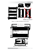


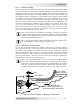


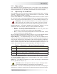
Table Of Contents

© 2017 Sensata Technologies 13
I nsta llat ion
2 .4 .6 W iring t he I nve rt e r t o t he Bat tery Ba nk
CAUTI ON : The inverter is NOT reverse polarity protected—if the
positive terminal of the battery is connected to the negative terminal
of the inverter and vice versa, severe damage to the
inverter will
occur and this will void the warranty. Before connecting the DC
wires from the batteries to the inverter, verify the correct battery
voltage and polarity using a voltmeter. Color code cables [red =
positive (+), white = negative (–)] to avoid polarity confusion.
I nfo: The DC overcurrent device (i.e., circuit breaker or fuse) must
be placed in the positive (red) DC cable line between the inverter’s
positive DC terminal and the battery’s positive terminal (red)—as
close to the battery as possible. For maximum protection, install
it within 18” (45 cm) of the battery. Note: For Marine applicat ions,
inst all wit hin 7” (17.8 cm ) of bat t ery.
Follow the st e ps be low t o w ire the inve r t er to t he bat t e r y bank :
1. Route an appropriately sized DC negative wire (marked white) from the
negative terminal of the battery bank to the inverter’s negative terminal
(Item 12, Figure 1-2).
2. Mount the fuse/disconnect assembly (or circuit breaker) as near as
practical to the batteries and leave open (i.e., no power to inverter).
W ARN I N G: DO NOT close the DC circuit breaker or connect
the fuse to connect battery power to the inverter at this time.
This will occur after the installation is complete.
CAUTI ON : If connecting live battery cables to the inverter DC
terminals, a brief spark or arc may occur; this is normal and
due to the inverter’s internal capacitors being charged.
3. Route and connect an appropriately sized DC positive wire (marked red)
from the inverter’s positive DC terminal (Item 11, Figure 1-2) to one
end of the fuse/disconnect assembly (or circuit breaker).
4. Connect a short wire (same rating as the DC wires) to the other side of
the DC circuit breaker (or one end of the fuse/disconnect assembly) and
the other end of that short wire to the positive terminal of the battery
bank (see Figure 2-1 or Figure 2-2 for reference). This is essential to
ensure even discharging across the entire battery bank.
5. Ensure DC wire connections (on batteries, inverter, and DC circuit
breaker/fuse) are fl ush on the surface of the DC terminals, and all the
connecting hardware are stacked correctly (see Figures 2-5 and 2-6).
Verify all DC connections on the inverter are torqued correctly (see
Table 2-1), and the total cable distance from the inverter to the battery
is within the requirement of Section 2.4.1 (DC Wire Sizing).
6. Once the DC connections are completely wired and tested, coat the
terminals with an approved anti-oxidizing spray.
7. If batteries are in an enclosure, perform a fi nal check of the connections
to the battery terminals, then close and secure the battery enclosure.
8. Route an appropriately sized DC ground wire (see Table 2-1) from the
inverter’s DC chassis ground connection to a dedicated system ground.
9. Once entire installation is complete and all connections verifi ed, close
the fuse disconnect (or circuit breaker) to provide power to the inverter.