
Owners Manual
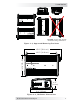


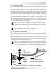


Table Of Contents

12 © 2017 Sensata Technologies
I nsta llat ion
2 .4 .5 W iring t he Ba t t er y Bank
W ARN I N G: Lethal currents will be present if the positive and
negative cables attached to the battery bank touch each other.
During the installation and wiring process, ensure the cable ends
are insulated or covered to prevent touching/shorting the cables.
I nfo: DO NOT connect the DC wires from the battery bank to
the inverter until 1) all DC wiring is complete, 2) the correct DC
overcurrent protection has been installed, and 3) the correct DC
voltage and polarity have been verifi ed.
Depending upon battery voltage (6, 12, or 24 VDC), the batteries must be
wired in series, parallel, or series-parallel to provide the correct voltage. The
interconnecting DC wires must be sized and rated exactly the same as those
used between the battery bank and the inverter.
Place the batteries as close as practical to the inverter, preferably in an
insulated and ventilated enclosure. Allow adequate space above the batteries
to access the terminals and vent caps (as applicable). Also, allow at least 1”
(2.5 cm) of space between the batteries to provide good air fl ow. DO NOT
mount the batteries directly under the inverter.
CAUTI ON : Install batteries in a well ventilated area. Batteries
can produce explosive gasses. For compartment or enclosure
installations, always vent batteries to the outside.
I nfo: To ensure the best performance from your inverter system,
batteries should be of the same size, type, rating, and age. Do not
use old or untested batteries.
DC cable
with ring lug
Inverter’s DC
negative terminal
M8 x 1.25 hex nut
CAUTI ON :
Ensure nothing is placed
between the DC terminal
and the ring lug.
CSW2024
Inverter
Lock washer
#12 Flat washer
Figur e 2 - 6 , DC Ca ble to I nver t er ’s D C Ter m ina ls