
Owners Manual
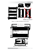


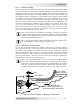


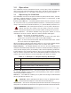
Table Of Contents

© 2017 Sensata Technologies 11
I nsta llat ion
2 .4 .3 DC Grou nding
The inverter should always be connected to a permanent, grounded wiring
system. The idea is to connect the metallic chassis of the various enclosures
together to have them at the same voltage potential and to reduce the
possibility for electric shock. For most installations, the inverter chassis and
the negative battery conductor are connected to the system’s ground bond
via a safety grounding conductor (bare wire or green insulated wire) at only
one point in the system. The grounding conductor for the DC system shall
meet the sizing requirements specifi ed in the NEC for the application, but
must be no smaller than
8 AWG (8.4 mm
2
) copper. For instance: An invert er
used in a m arine applicat ion under ABYC guidelines requires the size of t he
DC grounding conduct or to be of an am pacity equal t o or one size less t han
that of t he DC positive conductor. See Table 2-1 for the minimum ground
wire size recommended for your inverter.
I nfo: If the inverter is installed in a vehicle, connect the battery
negative cable directly to the inverter’s negative terminal. DO NOT
connect the negative battery cable meant for the inverter to the
vehicle’s frame/safety ground.
I nfo: The DC grounding system could be the vehicle’s chassis, the
DC grounding bus, or the engine’s negative bus.
2 .4 .4 DC Cable Conne ct ions
Do not put anything between the battery cable ring lug and the battery
post (see Figure 2-5), or the fl at metal part of the inverter’s DC terminal
(see Figure 2-6). When connecting the battery cable, it should be placed
directly against the battery post or inverter terminal. Incorrectly installed
hardware causes a high resistance connection which could lead to poor
inverter performance, and may melt the cable and terminal connections.
See Table 2-1 for the torque requirements.
I nfo: The DC terminal and Hex nuts are made of stainless steel,
which has a high likelihood of galling or thread seizing while being
tightened—causing the bolts to strip or to snap/break off. To reduce
this risk, use an anti-seize lubricant, tighten the fasteners slowly
(at low rpms) without interruption, and apply only light pressure.
DC cable
with ring lug
Bolt
Flat
washer
Nut
Lock washer
Battery
post
Battery terminal
Verify that the
DC cable lugs are flush
with the battery terminals.
BAT TERY
Figur e 2 - 5 , DC Ca ble to Bat t er y Term inals