
Owners Manual


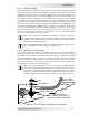


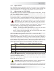
Table Of Contents

10 © 2017 Sensata Technologies
I nsta llat ion
Table 2 - 1 , DC W ire / Overcur re nt De vice for Rat ed Use
2 .4 .2 DC Over curr ent Prot ect ion
For safety reasons and to comply with electrical code regulations, DC
overcurrent protection must be provided as part of the installation. The DC
overcurrent protection device must be installed in the positive DC cable line,
it can be a fuse (with a disconnect switch) or a circuit breaker and must
be DC-rated. It must be correctly sized according to the size of DC cables
being used, which means it is required to open before the cable reaches its
maximum current carrying capability, thereby preventing a fi re. The NEC
requires both overcurrent protection and a disconnect switch.
Because batteries can deliver thousands of amps in an instant during a
short, you are required to install a DC-rated fuse (or circuit breaker) that
has a interrupt current rating (i.e., Amps Interrupting Current or AIC) that
can withstand the short-circuit current without explosion or damage. If
a fuse is used as an overcurrent device, a Class-T type or equivalent is
highly recommended when used with inverters. A Class-T fuse is rated for
DC operation, can handle very high short-circuit currents (up to 100,000
amps), and has a time delay that allows for momentary current surges from
the inverter without opening the fuse. In some installations, if the combined
short-circuit current of all the batteries in the bank is determined to be
2,700 amps or less, then an ANL type of fuse may be used—if in doubt, use
a Class-T fuse. Refer to Table 2-1 for the fuse size for your inverter.
CSW 2 0 2 4
Full Load Cur r e nt 95
amps
Max im um Cont inu ous Current
1
119 amps
Minim um D C Grou nd W ire Size
2
#8
AWG (8.4 mm
2
)
Minim um D C W ire Size
[ 1 6 7 °F/ 7 5 °C ra t ing in free air]
3
#2
AWG (33.6 mm
2
)
[170 amps]
Max im um D C Fuse Size 150 amps with time delay
I ncreased
size for lon ge r
distance
5 – 1 0 fe et
( 1 .5 – 3 m )
#1 AWG (42.4 mm
2
)
1 0 – 1 5 feet
( 3 – 4 .6 m )
#1/0 AWG (53.5 mm
2
)
N ot e
1
: Maxim um Cont inuous Current is based on the inverter’s cont inuous power
rat ing at t he lowest input voltage wit h an effi ciency factor.
N ot e
2
: The grounding conduct or for the DC syst em shall m eet the sizing
requirem ents specifi ed in the NEC for the application, but m ust be no sm aller than
2 AWG (33.6 m m
2
) copper. I n som e applicat ions, the DC grounding conductor is
required t o be no less than the wire size for the DC positive/ negative cables. For
Marine applications, t he DC grounding cable size m ay be one size sm aller than t he
m inim um size required for t he DC current- carrying conduct ors, and t he conduct or
m ust be no sm aller than # 10 AWG ( 5.3 m m
2
) .
N ot e
3
: Copper wire rat ed wit h 167°F ( 75°C) insulat ion at an am bient tem perat ure
of 86°F ( 30°C), wit h a mult iple cable fi ll fact or (0.8) derat ing ( if needed).