
Owners Manual
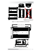


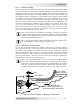


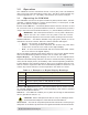
Table Of Contents

© 2017 Sensata Technologies 9
I nsta llat ion
Be aware that over-tightening or misthreading the nuts on the DC terminals
can cause the bolts to strip and snap/break off.
Make sure cables have a smooth bend radius and do not become kinked.
Follow existing wire runs where possible.
Crimped and sealed copper ring terminal lugs with at least a 1/4” (6 mm)
bolt hole to connect the DC wires to the inverter’s DC terminals.
The battery bank voltage MUST be between 21.0 – 31.0V for the inverter to
operate. If the voltage exceeds 32.0V, the inverter may be damaged.
To ensure the maximum performance from the inverter, all connections from
the battery bank to the inverter should be minimized. The exceptions are the
DC fuse and disconnect, or the DC circuit breaker—required at the battery to
protect the DC wiring—in the positive line. Any other additional connection
will contribute to additional voltage drops, and these extra connection points
may loosen during use.
When connecting the battery cables to the inverter DC terminals a brief
spark or arc may occur; this is normal and due to the inverter’s internal
capacitors being charged.
Before routing the wiring, color code the DC cables/wires with colored tape
or heat shrink tubing: RED for positive (+); WHITE for negative (–); and
GREEN (or bare copper) for DC ground, to avoid polarity problems.
A cable should be connected directly from the inverter negative terminal
to the battery negative connection; this ensures the inverter has a reliable
return path directly to the battery. Do not use the chassis in place of the
battery negative connection to the inverter.
2 .4 .1 DC W ire Sizing
It is important to use the correct sized DC wire to achieve maximum
effi ciency from the system and to reduce fi re hazards associated with
overheating. Always keep your wire runs as short as practical to prevent
low voltage shutdowns and to keep the DC breaker from nuisance tripping
(or open fuses) because of increased current draw. See Table 2-1 to select
the minimum DC wire size (and corresponding overcurrent device) required
based on your inverter model. The cable sizes listed in this table are required
in order to reduce stress on the inverter, minimize voltage drops, increase
system effi ciency, and ensure the inverter’s ability to surge heavy loads.
If the distance from the inverter to the battery is >5 feet (1.5 m), the DC
wire needs to be increased. Longer cable distances can affect the inverter’s
performance. See the lower part of Table 2-1 to determine the minimum DC
wire size needed for various distances >5 feet (1.5 m).
N ot e: I n an OEM RV applicat ion, a sm aller DC wire (wit h appropriate overcurrent
protect ion) m ay be used if t he invert er will only be connect ed to a dedicat ed
load ( as shown in Figure 2- 2) , and the invert er and dedicated load have been
thoroughly test ed and sold t ogether by t he OEM as a com plet e syst em .