
Owners Manual


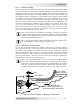


Table Of Contents

8 © 2017 Sensata Technologies
I nsta llat ion
2 .3 W iring t he I nvert er – Genera l Requirem ent s
This section describes the requirements and recommendations for wiring the
CSW2024 inverter. Before wiring the inverter, carefully read all instructions.
W ARN I N G: Wiring should meet all local codes/standards and be
performed by qualifi ed personnel (i.e., licensed electrician).
2 .3 .1 W iring Requirem ent s
• All conductors that are at risk for physical damage must be protected
by tape or placed in a raceway.
• Always check for existing electrical, plumbing, or other areas of
potential damage prior to making cuts in structural surfaces or walls.
• Where DC wiring must cross AC or vice-versa, try to make the wires at
the crossing point perpendicular (90 degrees) to one another.
• DC overcurrent protection must be provided as part of the installation.
• Use only copper wires with a minimum temp rating of 167°F (75°C).
• Ensure all conductor insulation is of a type that is approved for the
voltage, operation, temperature and location of use.
2 .3 .2 Tor que Requirem ent s
All wiring to the DC terminals and DC ground connection should be checked
periodically (once a month) for proper tightness. Tighten the DC terminals
and ground connections from 8.8 to 9.6 lbf-ft (12 to 13 N-m). If you don’t
have a torque wrench, ensure all connections are tight.
2 .4 DC W iring
This section describes the inverter’s required DC wire sizes, the recommended
disconnect/overcurrent protection, and how to make the DC connections to
the inverter and the battery bank.
W ARN I NG: Even though DC voltage can be regarded as “low
voltage”, signifi cant hazards may be present, particularly from short
circuits of the battery system.
CAUTI ON : The inverter is NOT reverse polarity protected—which
means if the negative and positive battery voltage is connected to
the inverter backwards, the inverter will likely be damaged. Use
a voltmeter to verify the correct polarity BEFORE connecting the
DC wires.
CAUTI ON : DO NOT connect the battery cables to the inverter until
all wiring is complete and the correct DC voltage and polarity have
been verifi ed.
Refer to Figure 2-5 when connecting the DC wires to the battery, and to
Figure 2-6 when connecting to the inverter.
Consider the follow ing to e nsure m ax im um perform a nce:
The DC positive and negative cables connected to the inverter from the
battery bank should be tied together with wire ties/straps or electrical tape
approximately every 6” (15.3 cm). This helps improve the surge capability
and reduces the effects of inductance, which improves the inverter waveform
and reduces the wear of the inverter’s fi lter capacitors. Keeping the battery
cables close together also reduces the chance of radio frequency interference.