
Owners Manual
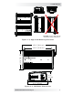


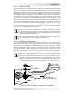


Table Of Contents

6 © 2017 Sensata Technologies
I nsta llat ion
2 .2 Loca t ing and M ount ing t h e I nvert e r
W ARN I N GS:
• Do not mount the inverter near any flammable or combustible
fluid or components.
• Provide adequate clearance/ventilation to the inverter. Do not
cover or obstruct any air vent openings and/or install in a zero-
clearance compartment.
The inverter should only be installed and mounted in a location that meets
the following requirements:
Clea n an d dr y – The inverter should not be installed in an area that allows
dust, fumes, insects, or rodents to enter or block the inverter’s ventilation
openings. This area also must be free from any risk of condensation, water,
or any other liquid that can enter or fall on the inverter.
Inverter failure
under these conditions is not covered under warranty.
Cool – The inverter should be protected from direct exposure to the sun or
to any equipment that produces extreme heat. The ambient temperature
should be between 32°F (0°C) and 104°F (40°C); note that the inverter’s
output specifi cations are rated at 77°F (25°C), so the cooler the better.
Ve nt ilat ed – In order for the inverter to provide full output power and
avoid over-temperature fault conditions, do not cover or block the inverter’s
ventilation openings, or install this inverter in an area with limited airflow.
Allow a minimum airspace clearance of 3” (7.6 cm) around the unit to
provide optimum ventilation.
Safe – Keep any flammable/combustible material (e.g., paper, cloth, plastic,
etc.,) that may be ignited by heat, sparks, or flames at a minimum distance
of 2 feet (60 cm) away from the inverter. Do not install in any area that
contains extremely flammable liquids like gasoline or propane, or in locations
that require ignition-protected devices.
Close t o the bat t ery bank – As with any inverter, it should be located as
close to the batteries as possible. Long DC wires tend to lose efficiency and
reduce the overall performance of an inverter. However, the unit should not
be installed in the same compartment as the batteries or mounted where it
will be exposed to gases produced by the batteries. These gases are corrosive
and will damage the inverter; also, if these gases are not ventilated and if
allowed to collect, they could ignite and cause an explosion.
Accessible – Do not block access to the front or back of the inverter. Allow
room to view any indictors or digital display and to access the AC and DC
wiring connections—they will need to be checked and tightened periodically.
Orient a t ing t he inve r t er – The CSW2024 inverter can be mounted on/
underneath a horizontal surface (shelf or table), or on a vertical surface (wall
or bulkhead) with the DC terminals facing left, right, or up—do not mount
with the DC terminals facing downward (see Figure 2-3).
After determining your mounting position, use the base of the inverter’s
chassis as a template to mark your mounting screw locations (or, refer to the
dimensions in Figure 2-4). Remove the inverter and drill pilot holes into the
mounting surface. Secure the inverter to the surface using the appropriate
corrosion-resistant hardware. If this unit is used in a mobile application, you
may want to place flexible washers or bushings between the mounting surface
and the inverter’s mounting flanges to reduce vibration.