
Owners Manual


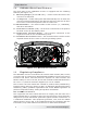

Table Of Contents

© 2017 Sensata Technologies 5
I nsta llat ion
Figur e 2 - 2 , RV OEM Syst e m Diagra m
CS W202 4 Power Inverte r
Serial Number
120 VA C 60 Hz, 200 0W / 16 .7A co nti nuous
Stat us
Po w er / Se l ec t
US B
Remot e
AC
Main Panel
(Branch Circuit
Breaker to
Transfer Switch:
20A max)
AC I N
AC OUT
AC Source
(120VAC, 60 Hz Sinewave)
CSW 2 0 2 4
I nver t e r
N ot es: The NEC requires overcurrent
protection for wiring and equipment
in both AC and DC circuits. As shown
in this diagram, the RVIA allows the
following application where an
inverter is installed in a RV.
Pass-thru m ode: When the AC source
(generator or shorepower) powers
loads thru a transfer switch (i.e.,
pass-thru mode), the conductor from
the transfer switch to the dedicated
load will be protected as long as the
branch rated circuit breaker at the
AC source does not exceed the
ampacity of the conductor feeding
the dedicated load.
I n vert er m ode: When the inverter is
powering loads using power from the
battery (i.e., Inverter mode), the
conductor from the inverter output to
the dedicated load will be protected
as long as the ampacity of the
conductor is sized based on the
inverter’s AC output rating. In
Inverter mode, the inverter has
overcurrent protection to limit the
output current and to protect the
conductor.
Dedicated
AC Load
(20A max)
DC
Disconnect
Fuse
DC
Ground
(Vehicle
chassis, DC
ground bus,
or engine
negative bus)
CSW - TS2 0
AC Transfer Switch
N ot e: A 24-volt charging
system is required to char ge
the battery bank when the
batt er y is discharged.