
Installation guide


254 Servo Drive
Apply voltage
Measure
system gain
!! Motor may turn !!
Execute move
using updated
controller gains
SHUTDOWN
Update controller
with calculated
servo gains
2
0.0 %Kvff
100.0 voltsIntLim
1.024 ms
Sample
time
Step 3: Update
0.0 volts
30 hertz
Calculate servo gains
based on measured
system gain
0.0 revs/sec /v
2
System Gain
System Bandwidth
Step 2: Calculation
.768 secs
Display
time
Disable integrator during motion
TrapezoidalProfile
22.5769 mv/cntKp
18.0467 msKi
9.0234 msKd
0.0 v/cnt/m sKaff
100.0Accel
100.0Decel
10.0 units/secSpeed
10.0 unitsMove
units/sec
2
units/sec
2
Step 1: Measure Step 4: Response
0.0 ms 768.00 ms 768 ms
Freeze scale
Print
Graph setup
Save graph
Zoom
-.318
.318
0.0
Left cursor
0.000 ms
Right cursor
768.000 ms
View Logged Data
_ X
5.0
Distance Limit - units
10.0
Speed - units/sec
2.0
Output - volts
1Servo axis
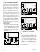
Response if the programmed speed is too
high for the motor. This also can be caused
by the drive running at too low a bus voltage.
Axis 1 Position error (units)
Quit
Apply voltage
Measure
system gain
!! Motor may turn !!
Execute move
using updated
controller gains
SHUTDOWN
Update controller
with calculated
servo gains
2
0.0 %Kvff
100.0 voltsIntLim
1.024 ms
Sample
time
Step 3: Update
0.0 volts
30 hertz
Calculate servo gains
based on measured
system gain
0.0 revs/sec /v
2
System Gain
System Bandwidth
Step 2: Calculation
2.048 secs
Display
time
Disable integrator during motion
"S" curve = 16Profile
22.5769 mv/cntKp
18.0467 msKi
9.0234 msKd
0.0 v/cnt/m sKaff
100.0Accel
100.0Decel
10.0 units/secSpeed
10.0 unitsMove
units/sec
2
units/sec
2
Step 1: Measure Step 4: Response
0.0 ms 1024.00 ms 2048 ms
Freeze scale
Print
Graph setup
Save graph
Zoom
-10.025
10.025
0.0
Left cursor
512.000 ms
Right cursor
1586.000 ms
View Logged Data
_ X
5.0
Distance Limit - units
10.0
Speed - units/sec
2.0
Output - volts
1Servo axis
Encoder velocity profile
Axis 1 Encoder velocity (units/sec)
Quit
Apply voltage
Measure
system gain
!! Motor may turn !!
Execute move
using updated
controller gains
SHUTDOWN
Update controller
with calculated
servo gains
2
0.0 %Kvff
100.0 voltsIntLim
1.024 ms
Sample
time
Step 3: Update
0.0 volts
30 hertz
Calculate servo gains
based on measured
system gain
0.0 revs/sec /v
2
System Gain
System Bandwidth
Step 2: Calculation
2.048 secs
Display
time
Disable integrator during motion
"S" curve = 16Profile
22.5769 mv/cntKp
18.0467 msKi
9.0234 msKd
0.0 v/cnt/m sKaff
100.0Accel
100.0Decel
10.0 units/secSpeed
10.0 unitsMove
units/sec
2
units/sec
2
Step 1: Measure Step 4: Response
0.0 ms 1024.00 ms 2048 ms
Freeze scale
Print
Graph setup
Save graph
Zoom
-10.0
10.0
0.0
Left cursor
512.000 ms
Right cursor
1586.000 ms
View Logged Data
_ X
5.0
Distance Limit - units
10.0
Speed - units/sec
2.0
Output - volts
1Servo axis
Command velocity profile
Axis 1 Command velocity (units/sec)
Quit
Apply voltage
Measure
system gain
!! Motor may turn !!
Execute move
using updated
controller gains
SHUTDOWN
Update controller
with calculated
servo gains
2
0.0 %Kvff
100.0 voltsIntLim
1.024 ms
Sample
time
Step 3: Update
0.0 volts
30 hertz
Calculate servo gains
based on measured
system gain
0.0 revs/sec /v
2
System Gain
System Bandwidth
Step 2: Calculation
1.280 secs
Display
time
Disable integrator during motion
TrapezoidalProfile
22.5769 mv/cntKp
18.0467 msKi
9.0234 msKd
0.0 v/cnt/m sKaff
100.0Accel
100.0Decel
10.0 units/secSpeed
10.0 unitsMove
units/sec
2
units/sec
2
Step 1: Measure Step 4: Response
0.0 ms 1280.00 ms 1280 ms
Freeze scale
Print
Graph setup
Save graph
Zoom
-9.9951
9.9951
0.0
Left cursor
0.000 ms
Right cursor
1280.000 ms
View Logged Data
_ X
5.0
Distance Limit - units
10.0
Speed - units/sec
2.0
Output - volts
1Servo axis
Response of the torque command for the
previous profile with speed set too high.
Note that the torque command saturates at 10
volts. Any time the command goes + or -10V,
the motor is not producing the required
torque to bring the error down.
Axis 1 Analog output / Torque (volts)
Quit