
Installation guide


250 Servo Drive
9.1.1.6 - Manual Tuning Adjustment
Most applications work acceptably using the results of the
auto tuning procedure. However, if the results of the auto
tuning sequence do not yield a satisfactory move re-
sponse, the servo gains may be adjusted manually to
achieve the required performance. Manual tuning of the
servo can be quite involved. Be sure to read this section a
few times through before deciding to begin manual ad-
justments.
The single most important rule to remember when ad-
justing the servo manually is to
gradually
change one
gain at a time
. There can be interactions between the
parameters that will affect the response, and changing
more than one gain at a time will certainly lead to confu-
sion.
First let’s begin with some definitions along with a de-
scription of each parameter and its function. The control
loop uses a modified
PID
algorithm to compensate the
system response. The servo parameters adjust the con-
troller’s output torque command based on
position error
,
i.e. the difference between commanded position and en-
coder position at any given point in time. The
encoder
velocity
and
commanded velocity
are also used in some
cases. Each parameter contributes to the output torque
command in a different way.
Stability or instability:
If the servo system behaves smoothly and without loud
buzzing, vibration or oscillation it is said to be
stable.
Conversely, if the system buzzes, vibrates, or oscillates
it is said to be
unstable
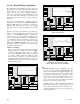
. The first goal of servo tuning
is to achieve a stable system. Once stable the system
may be adjusted or “tweaked” to optimize performance.
Adjustments should only be made if the response is out-
right unacceptable. The figures below show a stable and
unstable system response.
Kp:
Proportional gain
. This gain is multiplied by the posi-
tion error and thus contributes
proportionally
to the
output torque. Generally, the higher the Kp, the lower
the error at any time during the move. However, if Kp
is too high, the system can overshoot severely or “buzz”
loudly. This type of buzzing instability may be seen as
“grass” on the error response curve in the move re-
sponse screen. In this case, Kp should be lowered. Kd
may also be lowered, but to a lesser extent
.
Generally the range for Kp is 10 to 150. Kp less than 10
will usually produce a soft or sluggish system. Kp over
175 produces a stiff system, but one that may be ap-
proaching instability. Note these are general ranges, not
absolute requirements.
Apply voltage
Measure
system gain
!! Motor may tu rn !!
Execute move
using updated
controller gains
SHUTDOWN
Update controller
with calculated
servo gains
2
70.0 %Kvff
100.0 voltsIntLim
1.024 ms
Sample
time
Step 3: Update
0.0 volts
30 hertz
Calculate servo gains
based on measured
system gain
0.0 revs/sec /v
2
System Gain
System Bandwidth
Step 2: Calculation
.768 secs
Display
time
Disable integrator during motion
TrapezoidalProfile
22.0897 mv/cntKp
18.0467 msKi
9.0234 msKd
0.0 v/cnt/msKaff
100.0Accel
100.0Decel
10.0 units/secSpeed
10.0 unitsMove
units/sec
2
units/sec
2
Step 1: Measure Step 4: Response
0.0 ms 768.000 ms 768.0 ms
Freeze scale
Print
Graph setup
Save graph
Zoom
-.0625
.0625
0.0
Left cursor
0.000 ms
Right cursor
768.000 ms
View Logged Data
_ X
5.0
Distance Limit - units
10.0
Speed - units/sec
2.0
Output - volts
1Servo axis
Shows stable response
Axis 1 Position error (units)
Quit
Apply voltage
Measure
system gain
!! Motor may turn !!
Execute move
using updated
controller gains
SHUTDOWN
Update controller
with calculated
servo gains
2
50.0 %Kvff
100.0 voltsIntLim
1.024 ms
Sample
time
Step 3: Update
0.0 volts
30 hertz
Calculate servo gains
based on measured
system gain
0.0 revs/sec /v
2
System Gain
System Bandwidth
Step 2: Calculation
.768 secs
Display
time
Disable integrator during motion
TrapezoidalProfile
21.0306 mv/cntKp
3.0 msKi
9.0234 msKd
0.0 v/cnt/m sKaff
100.0Accel
100.0Decel
10.0 units/secSpeed
10.0 unitsMove
units/sec
2
units/sec
2
Step 1: Measure Step 4: Response
0.0 ms 768.000 ms 768.0 ms
Freeze scale
Print
Graph setup
Save graph
Zoom
-.09525
.09525
0.0
Left cursor
0.000 ms
Right cursor
768.000 ms
View Logged Data
_ X
5.0
Distance Limit - units
10.0
Speed - units/sec
2.0
Output - volts
1Servo axis
Shows unstable response
(due to Ki to low)
Axis 1 Position error (units)
Quit
Apply voltage
Measure
system gain
!! Motor may turn !!
Execute move
using updated
controller gains
SHUTDOWN
Update controller
with calculated
servo gains
2
75.0 %Kvff
100.0 voltsIntLim
1.024 ms
Sample
time
Step 3: Update
0.0 volts
30 hertz
Calculate servo gains
based on measured
system gain
0.0 revs/sec /v
2
System Gain
System Bandwidth
Step 2: Calculation
.768 secs
Display
time
Disable integrator during motion
TrapezoidalProfile
75.0 mv/cntKp
18.0467 msKi
30.0 msKd
0.0 v/cnt/m sKaff
100.0Accel
100.0Decel
10.0 units/secSpeed
10.0 unitsMove
units/sec
2
units/sec
2
Step 1: Measure Step 4: Response
0.0 ms 768.000 ms 768.0 ms
Freeze scale
Print
Graph setup
Save graph
Zoom
-.093
.093
0.0
Left cursor
0.000 ms
Right cursor
768.000 ms
View Logged Data
_ X
5.0
Distance Limit - units
10.0
Speed - units/sec
2.0
Output - volts
1Servo axis
Shows unstable response
(due to Kp and/or Kd too high)
Note "fuzz" from motor "buzzing"
Axis 1 Position error (units)
Quit