
Installation guide


Servo Drive 245
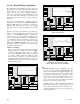
9.1.1.2 - Encoder Folder
This folder defines the Servo Encoder direction and En-
coder resolution.
Encoder type
m
ust be set to quadrature.
Encoder direction
determines how the encoder rotation
direction is interpreted. The choices are normal direction
or reverse direction. Use the default setting to start.
Encoder line count
defines the encoder resolution in
lines for a quadrature encoder. An Encoder with 1000
lines will provide 4000 counts/revolution, or quadrature
counts. Set this value to the encoder line count of the ser-
vomotor.
Pulse count
defines the pulse count per motor revolution.
This value is always 4 times the Encoder line count. If the
encoder input is pulse and direction, the pulses/rev value
should be entered here.
9.1.1.3 - Servo Drive Folder
This folder allows the user project servo drive parameters
to be modified. The PID loop gains, acceleration feed
forward gain, velocity feed forward gain, integral limit,
following error, sample time, and enable/disable integra-
tion during motion. The default settings for this folder are
suggested before tuning the servo drive.
This folder is modified during auto or manual tuning of a
servo drive and requires compilation and downloading of
the project to save the tuning settings.
Proportional gain
This gain is multiplied by the position error and thus
contributes
proportionally
to the output torque.
Generally, the higher the Kp, the lower the error at
any time during the move. However, if Kp is too
high, the system can overshoot severely or “buzz”
loudly. This type of buzzing instability may be seen
as “grass” on the error response curve in the move re-
sponse screen. In this case, Kp should be lowered. Kd
may also be lowered, but to a lesser extent.
Generally the range for Kp is 10 to 150. Kp less than
10 will usually produce a soft or sluggish system. Kp
over 175 produces a stiff system, but one that may be
approaching instability. Note these are general
ranges, not absolute requirements.
Integral gain
The reciprocal (1/Ki) of this term is multiplied by the
sum
of the position error over time. The effect of Ki
is thus time related, and affects the steady state error.
The higher Ki, the longer it will take for the control-
ler to “integrate out” any steady state error. The ef-
fect of Ki is seen mostly at constant speed (including
standstill). Ki is NOT required for stability, and gen-
erally has a de-stabilizing effect on the system, espe-
cially if it is too low. If Ki is TOO LOW the system
may oscillate slowly and wildly back and forth like a
washing machine. Ki is required, if the system must
achieve a very low steady state error (within a few
counts).
The general range for Ki is 10 to 70. Ki less than 10
may lead to wild, low frequency oscillations. If
steady state error is not a consideration, Ki may be
set to zero. Ki is often disabled during motion to re-
duce overshoot at the end of the move.
Derivative gain
This term is multiplied by the encoder velocity at any
point in time. Generally, raising Kd will reduce over-
shoot in the move response, however, Kd is the term
most susceptible to “digital instability”. This is where
the quantification effects of the digital encoder feed-
back in conjunction with too high a Kd cause the
system to “buzz”.
The general range for Kd is 5 to 20. Kd less than 5
usually leads to an unstable system, Kd >20 usually
leads to “buzzing”.
Accel feed forward
Some controllers have a Kaff term. This term is mul-
tiplied by the commanded acceleration to contribute
to the output torque command. This term only takes
effect to reduce the error during acceleration and de-
celeration. Generally Kaff is less than 4. Most appli-
cations will run fine with Kaff set at zero.
0.0
Axis 1
Integral gain
(msec)
0.0 0.0
Accel feed forward
(volts/count/msec )
Proportional
gain
(millivolts/count)
0.05
Derivative gain
(msec)
Velocity feed
forward (%)
enabled
0.0
100.0
0.0
Axis 2
0.0
0.0 0.0 0.0
0.0
Axis 2
Axis 1
Integral limit
(volts)
100.0
Following error
(units)
0.05
Sample time
(milliseconds)
1.024 msec
1.024 msec
Integration
during motion
enabled
Servo drive
Servo drive
2
Encoder
direction
Axis 1
normal direction
Line count
(lines / rev)
500
Encoder
Encoder type
quadrature
pulse count
(pulses/rev)
2000
Axis 2 quadrature normal direction
500 2000