
Installation guide


Page I-34
Installation Guide
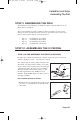
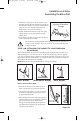
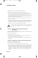
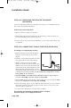
2. Determine your specific vertical elevation from the
Table (page I-50) and adjust the angular tilt of the
antenna so that the centre of the top bolt on the
Mast Head Clamp lines up with your vertical
elevation position on the Mast Head elevation
gauge. In our diagram here, it is set for 50 degrees.
3. Lightly tighten the two bolts located in the curved
slots on the mast head. Leave the pivot bolt
slightly loose.
4. Your antenna assembly is now ready to be placed
on the outdoor mount assembly.
The mount for attaching the dish to the dwelling is made of steel and, as a
result, it is very magnetic. If you are too close, it can adversely alter your
compass readings.
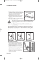
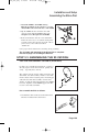
STEP 3.3B: ATTACHING THE MOUNT TO YOUR DWELLING
(90 CM DISH)
The mount should be attached to your dwelling before putting the dish assembly on it.
When fastening it to your wall or roof, etc., make sure that the top portion is plumb”.
You can get it right by using a spirit level on both the front and side of the top piece.
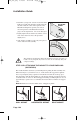
It is important to affix the mount firmly to your structure with the appropriate fasteners
so that the wind can’t move it. The dish support mounting assembly requires an area of
approximately 9 square feet to accommodate the mast mount foot and the two support
struts.
Note: Plumb means vertical in all directions. A flagpole is plumb.
WALL MOUNT HORIZONTAL MOUNT ROOF MOUNT
10
20
30
80
90
70
60
50
40
VERTICAL
ELEVATION
GAUGE
10
20
30
80
90
70
60
50
40
90˚
90˚
90˚
4100_Ins_eng 6/16/05 12:34 PM Page 38