
Spec Sheet

(Refer to product sheet for visual graphics)
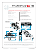
The Tamper bracket, containing the tamper switch
actuating magnet is inserted into the ANSI cutout first,
and secured with screws to the ANSI mounting tabs.
The Switch module is incorporated into the brass cover
plate and contains the Magnasphere alarm switch(es)
which are oriented toward the face of the Switch cover
plate towards the corresponding actuation magnet
mounted in the door, and the Magnasphere tamper
switch which is oriented in the opposite direction toward
the magnet in the Tamper bracket.
The cover plate is secured to the Tamper bracket via
mounting holes that are inboard on the cover and is
secured to corresponding mounting holes in the
Tamper bracket.
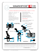
Any attempt to access the switch or wiring will require
removing the Switch module/cover plate. As this is
removed, the Tamper switch is moved away from magnet
in the stationary tamper bracket, which results in an
alarm condition.
This Tamper bracket – Switch module/cover plate
arrangement is also ideal when the device requires a
periodic test of the tamper circuit. The tester need only
loosen the mounting screws on the Switch module / cover
plate, pull the module out from its seated position and the
alarm switch will activate for the test.
(Refer to product sheet for visual graphics)
The Tamper device, containing the tamper switch
actuating magnet is a tapered “cap” that adheres to the
switch housing via double sided tape pads, and aligns the
tamper magnet opposite the tamper switch. The taper
allows the switch / tamper assembly to be inserted into
the 1” diameter mounting hole. Attempts to remove the
switch assembly, will result in the reverse taper “barbs” of
the tamper cap engaging the inside edge of the door
frame, and pulling the tamper cap tape pads loose from
the switch module. As this tamper cap / magnet releases
from the switch module, an alarm signal is generated.
NOTE:
The L2C switch module has locking side clips that make it
extremely difficult to remove the switch module without
damaging it. Therefore, removal of the switch to test the
tamper circuit is not recommended. If the L
2C is
used in
wood or aluminum door frame installations that require a
test of the tamper circuit, this can be accomplished by
using a specially magnetized L2C Tamper
Test Magnet
(Magnasphere part number 1384). Simply open the door
(which removes the L2C actuating magnet) and place the
Tamper Test Magnet beneath the switch – this will cause
activation of the tamper switch for the test.
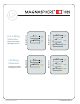
L2C-XXX Models for 1” Diameter Recessed Installation
L
2C-XXX-A Models for Use in Standard ANSI Door Cut Out
How the HSS L2C
Removal Tamper
Circuit Works
www.MAGNASPHERE.com
© MAGNASPHERE CORP.
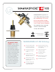
The MAGNASPHERE HSS L2C Series are the only
concealed devices available on the market that
incorporate a secure anti-tamper circuit. This
patented feature is available on both the ANSI cut
out and the 1” diameter recessed versions of the L2C.