
Installation Instructions

MAGNASPHERE HSS INSTALLATION INSTRUCTIONS: All Models of L2C-[XXX] Series
CAUTION: MAGNASPHERE MAGNET MODULES ARE EXTREMELY POWERFUL: TAKE PRECAUTIONS TO AVOID THE MAGNETIC ATTRACTION OF SHARP TOOLS
AND TO AVOID INJURY FROM THE PINCHING FORCE BETWEEN THE MAGNET AND FERROUS METALS OR OTHER MAGNETS.
Required Tools and Components
Provided by Manufacturer (per module set)
1 L2C switch module
1 L2C magnet module
2 #10 or #12 screws, magnet module
3 Spacers, magnet module
1 Tamper bracket
Provided by Installer
Blade screwdriver or a blade bit for use in the drill/bit-driver
RTV Adhesive for some sites (review instructions below)
Additional 1/32” SPACERS as needed (10 / BAG – MAGNASPHERE P/N 1222)
Door & frame as prepared in figure below †
Tamper Test Magnet: optionally used for non-invasive tamper switch tests P/N 1384
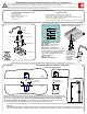
Installation:
Plan to mount the switch module into the door frame. The magnet module should be be mounted opposed and
aligned to the switch, within the door. Recommended placement for the set is 8 inches from the latch side of the
door, at the top. A gap up to 1/16" (1.6mm) is recommended though the switch can be installed to a
1/8" (3.2mm) maximum operating gap. For UL compliance, the installation must be in a metal frame with a
5/8" (minimum) door stop; the modules must have an operating gap no greater than 1/8".
Recommended Minimum Clearances and Features
for Door & Frame Cutouts
† It is not necessary to make allowance for the face-plate/flange of the magnet module if it fits with the switch module flange in the door-to-
frame gap.
*Recommended placement to meet door-opening, alarm, & nuisance alarm requirements of UL634 Level 2 standard. This guide is one
means to meet this standard. Installations which fulfill this standard are not restricted to the specific recommendations in this instruction set.
1
1
.08†
1.1
FRAME
DOOR
BEST PLACEMENT
0"-8" *
SEE FLANGE
ALLOWANCE NOTE
Specifications
Max Current: 0.25 A Resistive
Max Voltage: 30 VDC
Max Power: .25 W Resistive
The Magnasphere L2C series is intended
to be connected to a UL Listed compatible
control panel for US applications and a
ULC Listed compatible control panel for
Canadian applications.
Gap: 0" to 1/8"
Suitable for outdoor use
Test the Pry-Tamper
circuit here with an
L2C Tamper Test
Magnet (P/N #1384)
for installations in
non-ferrous
(aluminum)
environments
WHT
WHT
CLOSED
LOOP
BLK
BLK
CLOSED
LOOP
YEL
YEL
CLOSED
LOOP
MODEL L2C-111
CONTACT STATE SHOWN WITH MAGNET IN PLACE
ALARM
AUX
PRY
TAMPER
L2C SERIES
LEVEL 2 CONCEALED: High Security
contacts for recessed mounting
FRAME
SECTION
S
N
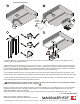
1
1
#8-32 x 1/2" dp
x2 PLCS
2 5/8†
FRAME
DOOR
1
1 3/4
SEE FLANGE
ALLOWANCE NOTE
SWITCH MODULE
TAMPER
BRACKET
#10 or #12 SCREW
#10 or #12 SCREW
MAGNET MODULE
1/32" SPACERS
Models having the following suffixes are equipped with pry-tampers, a requirement of UL634 High Security Levels 1 and 2: -101, -111
Attention: modules à aimants Magnasphere et anti-enlèvement aimants sont très puissants: prendre des précautions pour éviter l'attraction magnétique d'outils tranchants et
à éviter les blessures de la force de pincement entre l'aimant et les métaux ferreux ou d'autres aimants.