
Manual


Installation
MKG Series Gas Griddle
L25-052 R3 (04/12)
8
1.6. Final Gas Connection
A properly installed gas supply system will deliver adequate pressure, between 7 and 8 inches w.c. (1.75-2.0 kPa)
for natural gas, or 11 to 12 inches w.c. (2.7-3.0 kPa) for propane to all appliances connected to the line, operating
at full demand.
1.6.1. Regulator Assembly
An adequate gas supply is important for the appliance to operate properly. Undersized lines or low-pressures will
restrict the volume of gas required for satisfactory performance. A steady supply pressure between 7” and 8” w.c.
(1.75-2.0 kPa) for natural gas or 11” to 12” (2.7-3.0 kPa) for propane gas is required. With all gas appliances
operating simultaneously, the manifold pressure on all gas appliances should not show any appreciable drop.
Fluctuations of more than 25% on natural and 10% on propane gas will create pilot problems and affect burner
operating characteristics. Contact your gas company for correct supply line sizes. After connection, a certified gas
service agent should check all newly installed equipment for correct gas pressure. The unit should be connected
ONLY to the type of gas for which it is equipped. Check the gas type on the Data plate; see section 1.1 of this
manual.
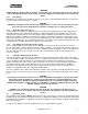
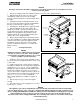
Figure 6
1. The gas input regulator for your new appliance have been installed at the factory, See Figure 6 for the
location of the regulator manual shut off valve equipped on your appliance. Using a regulator other than the
one supplied with the unit will void the warranty.
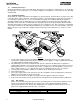
2. The manifold pressure must be maintained at the pressure marked on the Data plate. For appliances
equipped with Solid State or Electric Thermostat controls the pressure reading is taken at the pressure test
point supplied on the ¾”
(19 mm) manual shut off valve, see Figure 6. For all other griddles, a pressure test
point is supplied on the ½”
(13 mm) manual shut off valve located behind the door, also see Figure 6.
3. Use pipe joint compound that is suitable for use with LP gas on all threaded connections.
4. Turn off all thermostats.
5. Turn on gas supply and check all connections for leaks using ONLY a leak checking fluid or soapy water.
NEVER use an open flame to check for gas leaks.
6. Provision must be made for adequate air supply for both the appliance and room occupants.
7. Keep area in front of unit free from obstructions that could block flow of combustion and/or ventilation air.
1.6.2. Gas Settings
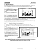
Orifices are sized to provide proper gas flow to the rated input power for each model. Regulator pressure
must be measured and adjusted before the unit goes into service, following installation and when
operational performance is in question. The manifold pressure readings are taken at the pressure test
points on the supplied manual shut off valves, see Figure 6.
Gas Type BTU/hr (kW) (MJ/h) per Burner Manifold Pressure (All Models)
Natural 15,000 (4.4) (15.8) 4.0" WC (10 mbar) (1.0 kPa)
Propane 15,000
(
4.4
)
(
15.8
)
10.0" WC
(
25 mbar
)
(
2.5 kPa
)