
Manual


Installation
MKG Series Gas Griddle
L25-052 R3 (04/12)
7
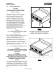
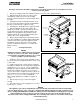
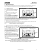
1/2" BOLTS (4)
BRACKET (2)
MOUNT FLUSH
TO FRONT
(SUPPLIED)
(SUPPLIED)
NUTS & BOLTS
INCLUDED
WITH STAND
REAR
Figure 4
NOTICE
The larger units have 6 threaded receiving holes, but require only the four 1/2" (13 mm) bolts on each
corner to mount the griddle.
1. Remove (4) existing 1/4-20 nuts and bolts from the rear corners of the equipment stand.
2. Align the 2 bolt holes on the rear corners of the
stand with the 2 bolt holes on the rear mounting
brackets. Orient the brackets as shown in Figure #4 on
this page.
3. Install the provided rear mounting brackets (2) to
the rear corners by using the existing 1/4-20 hardware
that were removed in step 1, tighten securely.
4. Carefully place the griddle on the equipment stand.
5. Once the griddle is on the stand, position the
griddle on the stand so that the front edge of the base
is flush with the front of the equipment stand. If the
griddle is the only appliance to be mounted on the
stand, then both sides of the griddle should be flush
with the sides of the equipment stand.
6. When positioned properly, the threaded receiving
holes in the griddle base should be aligned with mating
clearance holes at the front of the equipment stand,
and with the clearance holes in the rear mounting
brackets. Install the provided 1/2"
(13 mm) bolts and
tighten securely.
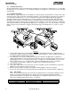
1.5.4. Leveling Instructions
NOTICE
Equipment stands are shipped from the factory with
the legs or casters set to “Zero”. Units should be
leveled at time of installation; failure to do so could
cause the griddle to operate improperly.
1. Identify the end or corner of the stand that needs to
be raised, remove the weight load from the caster or leg
to be leveled.
2. Legs- using a wrench, or pliers turn the leg bullet,
See Figure 5, CCW to raise the height of the equipment
stand. There is ½”
(13 mm) to ¾” (19 mm) of adjustment.
Casters- (For Stands shipped after May 2006) Using a
Flat Head screwdriver, loosen the set screws of the
caster to be leveled, See Figure 5.Turn the collar of the
caster CCW to raise the height of the equipment stand.
There is ½”
(13 mm) to ¾” (19 mm) of adjustment.
After leveling adjustment is complete, re-tighten set
screws.
3. Repeat Step 2 for legs or casters that require
leveling.
4. Check the levelness of the equipment, if necessary
Repeat steps 1, 2, and 3.
NOTICE
This appliance may only be installed with casters provided by the manufacturer. When installed with
casters in North America, a gas connection complying with ANSI Z21.69/CGA-6.16 and a quick disconnect
device complying with ANSI Z21.41/CAN 1-6.9. It must also be installed with a restraining device to guard
against putting any strain on the gas connections when the unit is moved. In Australia the quick
disconnect device must comply with AS4627. The restraining device must not exceed 80% of the length
of the flexible gas line.
Figure 5