
Manual


Installation
MKG Series Gas Griddle
L25-052 R3 (04/12)
6
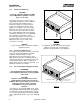
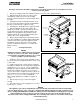
1.5.1. Counter Use With Legs
CAUTION
To prevent equipment damage, DO NOT
tilt your MagiKitch'n griddle on only two
legs, or on its sides.
(See Figure 2) A set of 4” (10.2 cm) legs is
shipped with the appliance (unless appliance
was specifically ordered without legs). A
threaded receptacle is located near each
corner of the underside of the base of the
appliance, on appliances 48" (122 cm) and
wider there are threaded receptacles in the
front and rear center of the base. Each leg
has a similar mating thread. Raise appliance
sufficiently to allow legs to be screwed tightly
into receptacles. The appliance can be
leveled by adjusting the feet at the bottom of
the leg assembly. This can be done by
turning the foot in or out to lower or raise
each corner as needed.
NOTICE
4" Legs should not to be used with the optional
Equipment Stand.
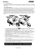
1.5.2. Counter Use Without Legs
(See Figure 3) The appliance must be sealed to the
counter to comply with applicable sanitation
standards. A bead of silicone sealant,
approximately ½ inch (13 mm) wide, is to be
applied to the bottom of the unit approximately ¼”
(7 mm) in from the front, back and side edges. We
suggest Dow Corning ®, GE ® or Permatex ®
silicone ‘RTV’ adhesive sealant or equivalent. (See
NSF Basic Criteria C-2 for details).
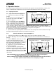
1.5.3. For Use On Optional Equipment Stand
ATTENTION
Rear mounting brackets should be installed
to the Equipment Stand prior to placing griddle
on the stand.
CAUTION
Only two of the four supplied casters are
equipped with a locking feature. Install the
griddle so that the two locking casters are at the
front of the unit. The casters should be
LOCKED before the unit is placed into
operation.
(See Figure 4). To mount the griddle to the stand,
locate joining kit supplied with stand. The joining kit
should include (2) rear mounting brackets, and (4)
1/2" (13 mm) mounting bolts. To mount the griddle
to the equipment perform the steps on the following
page:
Figure 2
CAUTION
The appliance must be level to perform properly.
Failure to level unit may result in improper
combustion and performance of the appliance.
Figure 3
LIQUID TIGHT SEAL
ALL FOUR SIDES
SIMULATED BASE