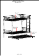
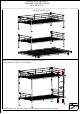
BUNK BED & TRUNDLE ASSEMBLY INSTRUCTIONS SKU MF291667 Weight Limit 250 Lbs Weight Limit 350 Lbs Weight Limit 250 Lbs PAGE 1 OF 12
BUNK BED & TRUNDLE ASSEMBLY INSTRUCTIONS SKU MF291667 SAFETY WARNING 1.This bed is designed for use only mattress (es) meeting the following specifications on the upper bunk, and lower bunk: Upper bunk (bunk bed and tribed included) Bed type Length Width Thickness Twin 74” – 75” 38½’’ 6’’ max Lower bunk Bed type Length Width Thickness Twin 74” – 75” 38½’’ 8’’ 2.Replacement parts, including additional guardrails, maybe obtained from any of our (GIGACLOUD TECHNOLOGY(USA) INC.
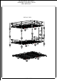
BUNK BED & TRUNDLE ASSEMBLY INSTRUCTIONS SKU MF291667 DETAIL VIEW 2 7 5 6 5 3 2 3 11 *2 12*19 4 10 4 4 9 5 1 1 1 12*19 14 5 11 *2 8 1 13 13 14 11 *2 12*17 PAGE 3 OF 12 4
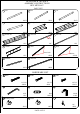
BUNK BED & TRUNDLE ASSEMBLY INSTRUCTIONS SKU MF291667 PART LIST 1 Post 2 Post 3 Post 4PCS 2PCS 6 Guard rail 5 End guard rail 4 Post 4PCS 7 Guard rail 2PCS 4PCS 8 Side rail 1PC 9 Side rail Holes 1PC 10 Ladder 1PC 11 Slats 1PC 12 Slats Screw hole 1PC 13 End rail Hollow 6PCS 55PCS 14 Side rail 2PCS 2PCS HARDWARE LIST A Bolts B Bolts C Bolts 1/4"*35 8PCS 1/4"*60 20PCS D Allen key F Connect wall E End cap 4*59 1PC 1/4*40 2 SET Ø42 16PCS I Hex nut H Caster G Locking Caster 1/4"*1
BUNK BED & TRUNDLE ASSEMBLY INSTRUCTIONS SKU MF291667 OPTION A STEP 1-9 STEP 1 : Following below illustration Assembly Frame #1.Using hardware #E, #C connect #1 , #2, #3, #4 with #5 to complete Frame #1. C*10 5 C C 3 2 4 4 C 10PCS 5 1 1/4*15 E 4PCS 1 E E*4 NOTE:In this step, DO NOT tighten any bolt until you connect all part together.
BUNK BED & TRUNDLE ASSEMBLY INSTRUCTIONS SKU MF291667 STEP 2 : Following below illustration Assembly Frame #2.Using hardware #E, #C connect #1 , #2, #3, #4 with #5 to complete Frame #2. C*10 5 C C 2 3 4 4 C 10PCS 5 1/4*15 E 4PCS 1 1 Ø42 D 1PC E E*4 NOTE:In this step, DO NOT tighten any bolt until you connect all part together. 4*59 STEP 3 : Following below illustration Assembly Frame #3. Using hardware #C connect #6, #7 with #11, #12 to complete Frame #3.
BUNK BED & TRUNDLE ASSEMBLY INSTRUCTIONS SKU MF291667 STEP 4 : Following below illustration Assembly Frame #4. Using hardware #C connect #8, #9 with #11, #12 to complete Frame #4. 9 8 12*19 11*2 C C 4PCS 1/4*15 D 1PC NOTE:In this step, DO NOT tighten any bolt until you connect all part together. 4*59 STEP 5 : Following below illustration Assembly Frame #5. Using hardware #A, #C connect Frame #1, Frame #2 with Frame #3, Frame #4 to complete Frame #5.
BUNK BED & TRUNDLE ASSEMBLY INSTRUCTIONS SKU MF291667 STEP 6 : Following below illustration Assembly Frame #6. Using hardware #A connect Frame #5 with #10 to complete Frame #6. A A*4 10 A 4PCS 1/4*60 D 1PC NOTE:In this step, DO NOT tighten any bolt until you connect all part together. 4*59 STEP 7 : Following below illustration Assembly Frame #7. Using hardware #F connect Frame #6 with Wall to complete . Wall F Wall F F 2 SET D NOTE: Tighten all step before using. Thank you.
BUNK BED & TRUNDLE ASSEMBLY INSTRUCTIONS SKU MF291667 STEP 8 : Following below illustration Assembly Frame #8. Using hardware #B, #C connect #11, #12, #13 with #14 to complete Frame #8. B*2 13 C 14 C B*2 B*2 14 13 B*2 12*17 C C 11*2 B 8PCS 1/4*35 C 4PCS 1/4*15 D 1PC NOTE:In this step, DO NOT tighten any bolt until you connect all part together. 4*59 STEP 9 : Following below illustration Assembly Frame #9. Using hardware #G, #H connect with Frame #8 to complete.
BUNK BED & TRUNDLE ASSEMBLY INSTRUCTIONS SKU MF291667 OPTION B STEP 10-14 STEP 10 : Following below illustration Assembly Frame #10. Using allen key D open #10 to complete. 10 D NOTE:In this step, DO NOT tighten any bolt until you connect all part together.
BUNK BED & TRUNDLE ASSEMBLY INSTRUCTIONS SKU MF291667 STEP 11 : Following below illustration Assembly Frame #11. Using allen key D open hardware C to complete. D NOTE:In this step, DO NOT tighten any bolt until you connect all part together. STEP 12 : Following below illustration Assembly Frame #12. NOTE:In this step, DO NOT tighten any bolt until you connect all part together.
BUNK BED & TRUNDLE ASSEMBLY INSTRUCTIONS SKU MF291667 STEP 13 : Following below illustration Assembly Frame #13. Using hardware #C, #I connect with Frame #12 to complete. I*4 C*4 C 4PCS D 1/4*15 1PC 4*59 I 4PCS NOTE:In this step, DO NOT tighten any bolt until you connect all part together. STEP 14 : Following below illustration Assembly Frame #14. Using hardware #E connect with Frame #13, #12 to complete. OPTION B FINAL E 8PCS NOTE: Tighten all step before using. Thank you.