Dishwasher Installation Manual Model MCSDW8TCST PLEASE READ THIS MANUAL CAREFULLY BEFORE USING YOUR DISHWASHER AND KEEP IT FOR FUTURE REFERENCE.
CONTENTS INTRODUCTION . . . . . . . . . . . . . . . . . . . . . . . . . . . . . . . . . . . . . . . . . . . . . . . . . . . . . . . . . . . . . 3 IMPORTANT SAFETY INSTRUCTIONS . . . . . . . . . . . . . . . . . . . . . . . . . . . . . . . . . . . . . . . . . . . 3 SPECIFICATIONS. . . . . . . . . . . . . . . . . . . . . . . . . . . . . . . . . . . . . . . . . . . . . . . . . . . . . . . . . . . . . . 5 PARTS AND MATERIALS . . . . . . . . . . . . . . . . . . . . . . . . . . . . . . . . . . . . . . . . . . . .
INTRODUCTION When using the dishwasher, follow carefully precautions in this instruction, especially the safety instructions. These are provided in order to save you, your time and effort and help to ensure optimum dishwasher performance. Be sure to observe all listed warnings and cautions. Look particularly for the icons with exclamation marks inside. The information icon will also provide important references.
• Connect to a properly rated, protected and sized power supply circuit to avoid electrical overload. The dishwasher is designed for an electrical supply of 120V, 60Hz AC, and should be connected to a dedicated, properly grounded 15 A circuit with a fuse or circuit breaker. These requirements must be met to prevent injury and damage to the unit. Consult a qualified electrician if in doubt. • This dishwasher includes a heating element. DO NOT touch the heating element during or immediately after use.
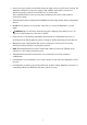
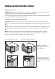
SPECIFICATIONS Figure 1 33 7/8"-35 7/8" (860 mm-910 mm) 23 9/ (598 m 16" m) 8" 4 1/ m) m (105 Load Capacity Permissible Water Pressure Electrical Connection Total Power Heater Power 23 5/ (60 mm8" ) 34"-36" (864-914 mm ) 70 16" 7/ mm) 2 2 70 (5 3 15/16" (100 mm) " /32 ) 1 31 mm (50 6" 7/1 ) 22 0 mm 7 (5 15 Place Settings 4.35 - 145 p.s.i. (0.
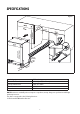
PARTS AND MATERIALS TOOLS THAT MAY BE NEEDED • • • • Pipe Wrench Hole Saw Tape Measure Adjustable Wrench • • • • • • • • Level Wire Cutter Hammer Torx Screwdriver Slot Screwdriver Phillips Screwdriver Drill Wire Stripper • • • Brush Scissors Pencil MATERIALS THAT MAY BE NEEDED • • • • Hot Water Supply Line – Min . 3/4” O.D. copper tubing or metal braided dishwasher supply line UL listed conduit connector or strain relief. Teflon tape or pip thread compound to seal plumbing connections.
INSTALLATION INSTRUCTIONS ELECTRICAL PREPARATION WARNING: The dishwasher is designed for an electrical supply of 120 V, 60 Hz, AC connected to a dedicated, properly grounded electrical circuit with a fuse or breaker rated for 15 Amps. The power-supply receptacle for the appliance shall be installed in a cabinet or on a wall adjacent to the under counter space in which the appliance is to be installed.
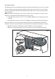
ADJUSTING THE HEIGHT The dishwasher must be leveled and balanced after it is placed into the cabinetry enclosure. Prior to it being placed in the final position, the leveling legs should be at the shortest position. There are 2 sets of leveling legs that are included with dishwasher. Carefully measure the height of the enclosure to determine which legs you should use.
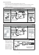
WATER SUPPLY CONNECTION The water supply may be connected in one of the following ways: 1. With braided metal hose 2. With copper tubing CAUTION: Hot water supply line: Use minimum 3/4" O.D. copper tubing or metal braided dishwasher supply line. The water Inlet valve of the dishwasher has a 3/4"-11.5NH inlet coupling thread dimension according to ASME B1.20.7-1991.
DRAIN HOSE CONNECTION 1. Check the parts on the sink to which the drain hose will be connected. 2. There are several ways to insert the drain hose into the drain hose connector of the sink, as shown in Figures 6 & 7. You must connect the drain hose in accordance with the water pipe installation regulations in your region.
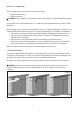
4. Slide a hose clamp over the end of the drain hose. Attach the Figure 8 drain hose to the sink connector, slide the hose clamp to the end of the hose, and then tighten the hose clamp. NOTE: You must use a hose clamp. Failure to do so may cause water leakage. 5. If there is no air gap, make sure to hang the middle of the drain hose well above the sink cabinet base to prevent back flow (see Figure 9). 6.
INSTALLING THE ADJUSTABLE TOE KICK Once the dishwasher is put into the enclosure, the toe kick needs to be installed. The two piece toe kick can be adjusted to the height and depth required for the placement of the dishwasher. Make sure the unit is plumb and level in the enclosure before installing the the toe kick. 1. Determine the height of the dishwasher to Figure 10 figure the adjustable plinth installation. a.
INSTALLER CHECKLIST The installer must have completed and checked the following: • The dishwasher is square and level. • The dishwasher is fastened securely to the cabinetry. • The dishwasher door opens and closes freely. The dishwasher door must close without hitting any cabinetry or counter top. • The inlet water supply is turned on and checked for leaks. • The drain hose has been connected and checked for leaks. There must be no kinks or obstructions in the drain hose.
CNA International, Inc. d/b/a MC Appliance Corporation. All rights reserved. Magic Chef® logo is a registered trademark of CNA International, Inc. www.mcappliance.