
Installation Guide


15
HOW TO CHECK OPERATION
How to Adjust Standard Burner
IMPORTANT: Adjustments must be made with two other burners in operation on a medium setting. This
prevents the upper row of the flames from being set too low, resulting in the flame being extinguished when other
burners are turned on.
1. Turn all burners on the highest setting and check the flames. The flames should all be blue in color (LP gas
will have blue flames with yellow tips). Foreign particles in the gas line may cause an orange flame at first, but
should disappear in a short period of time.
2. Light one burner and turn to the lowest setting.
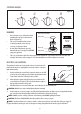
3. Remove the control knob to the desired burner that you wish to adjust.
4. Insert screwdriver through the access hole in the valve shaft. (Refer to Figure 20.)
5. Slowly turn the screw until the flame appearance is correct.
• If the flames are too small or fluttered, open the valve more than the original setting.
• If the flames are too large, close the valve more than the original setting.
Figure 20
Testing Flame Stability
• Test 1: Turn the control knob from “HI” to “LO” quickly. If the upper row of flames goes out at this setting,
increase the flame size and test again.
• Test 2: With the burner on “LO”, open and close the cabinet door under the cooktop. If the flame is
extinguished by the air currents created by the door movement, increase the flame height and re-test.
Flame Check
• After all the flame adjustments have been made, turn all burners to the off position.
• “LITE” each burner individually and observe the flame at the “HI” position.
• Rotate the burner knob to the lowest setting and be sure the flame size decreases as the knob is rotated
counter-clockwise.
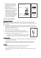
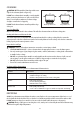
Figure 19
Not Properly
Seated
Properly
Seated
2. Place the burner caps on the burner
heads. Make sure the burner caps are
properly seated on the burner head.
(Refer to Figure 19.)
3. Operation of the electric ignitors
should be tested after the cooktop and
supply line have been carefully checked
for leaks and the cooktop has been
connected to the electrical power.
• To check igniters, push and turn a burner
valve to the light positon. All sparks will
make a series of sparks, but only the
burner turned to LITE with light.
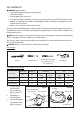
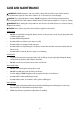
Figure 18
Burner Cap
Burner Head Assembly
Electrode
Burner Base