
User guide

Connector Pinouts
MultiView™ II T4 Installation and User Guide 14
Appendix A Connector Pinouts
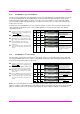
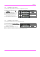
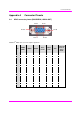
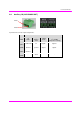
A.1 HD15 connector pinout (SOURCE IN, LOCAL-OUT)
.
MultiView
TM
HD15 video connector signal assignments:
Pin
RGBHV
(VGA)
RGBS RGsB
Com-
posite
SVHS
(Y/C)
YUV
Composite
Video &
Stereo
Audio
1
Red + Red + Red +
C+ V+ Audio Left
2
Green+ Green+ Green+ C+ Y+ Y+ C+
3
Blue+ Blue+ Blue+
U+ Audio Left
4
— — —
5
Gnd Gnd Gnd
6
Red- Red- Red-
C- V- Shield
7
Green- Green- Green- C- Y- Y- C-
8
Blue- Blue- Blue-
U- Shield
9
— — —
10
Gnd Gnd —
11
Gnd Gnd —
12
— — —
13
H Sync C Sync —
14
V Sync — —
15
Gnd Gnd —
Pin #
10
Pin #15 Pin #11
Pin #
6
Pin #5
Pin #
1