TM MultiView II T4 Transmitter Installation and User Guide Document # 5310188-02 Rev-01 (3/22/2012)
© 1998-2012 by Magenta Research, Ltd. All rights reserved. Magenta Research, Ltd. 128 Litchfield Road New Milford, CT 06776 USA This document and the Magenta Research Ltd. products to which it relates, and the copyright in each, is the property of Magenta Research Ltd. Neither the document nor the products may be reproduced by any means, in whole or in part, without the prior written permission of Magenta Research.
Precautions Precautions Safety Instructions ● English This symbol calls attention to important information. This symbol is intended to alert the user of important maintenance (servicing) and operating information. This symbol is intended to alert the user to the presence of un-insulated dangerous voltages or other conditions in or around the product enclosure which may present a risk of electric shock, damage to equipment or facilities.
Contact Information Contact Information For sales or technical support, contact your nearest Magenta Research sales office. Region North, Central and South Americas: Magenta Research, Ltd. Corporate Headquarters 128 Litchfield Road New Milford, CT 06776 USA Asia: Magenta Research Asia Limited Unit 1 21/F Cheung Tat Centre Chai Wan, Hong Kong Contact details Main: 800-805-0944 (USA only) or +1 860-210-0546 Fax: 1-860-210-1758 Web: www.magenta-research.com Sales: sales@magenta-research.
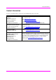
Table of Contents Table of Contents Page Chapter 1 About this Manual ...................................................................................................................... 1 Chapter 2 Product Overview....................................................................................................................... 2 2.1 Front Panel interfaces ..................................................................................................... 2 2.2 Rear Panel interfaces .............
About this Manual Chapter 1 About this Manual This manual contains information about the Magenta MultiView™ II T4 transmitter (hereafter referred to simply as “T4”). This includes: • • • • • Product overview (Chapter 2). Product specifications (Chapter 3). Installation and configuration instructions (Chapter 4) Troubleshooting (Chapter 5). Additional information (Appendices).
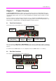
Product Overview Chapter 2 Product Overview The Magenta MultiView™ II T4 transmitter extends an analog video signal over standard CAT5 cable (also CAT5e and CAT6). It accepts analog video (VGA, RGB and other analog formats), audio (analog or S/PDIF) or serial (RS-232 simplex) signals. These are converted to MultiView™-compatible signals, provided over 4 UTP output ports. The T4 also features an enhanced front-panel interface for user-configuration and DDC/EDID management.
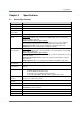
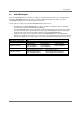
Specifications Chapter 3 3.1 Specifications General Specifications Item Description Cable Required Category 5, 5e, 6 cable. Shielded or unshielded twisted pair. Low-skew. Compliance CE, FCC Class A, IC Class / Class A, UL listed I.T.E Device, RoHS. Video Support RGBHV, RGB, Composite, S-Video, and Component Video modes. Resolution & Refresh Rate To 1920x1200 @ 70Hz. Maximum Distance To 2000 ft, receiver dependent. Interface Signal Details Video-input: Standard VGA (HD-15) video connection.
Specifications 3.2 DDC/EDID Support For best compatibility with source devices (ex: a PC), an extension device (T4 in this case) should provide an appropriate DDC/EDID profile with the proper resolution and timing information. This helps ensure best compatibility with display devices connected at the remote end.
Specifications 3.3 Auxiliary Signal Support The MVII-T4 design supports three types of auxiliary signals. Two are available pre-configured from the factory. The third option is easily user-selectable from the front-panel buttons. Note that only one type of signal is supported at a time: • • • Factory option, MVII-T4-A: o Supports L+R summed audio. Factory option, MVII-T4-S: o Provides simplex (TX-only) serial data, even with daisy-chained receivers. o Data is transmitted to all attached receivers.
Installation Chapter 4 Installation CAT5/5e/6 cabling for the Magenta MultiView™ II Series must be pinned to the TIA-EIA T568B wiring specification. Figure 1 T568B CAT5 Specification We also highly recommend that all CAT5 cables be pre-terminated and tested. Cables terminated on-site or in an existing infrastructure should be tested before use to ensure compliance with the TIA-EIA T568B specification. Using incorrectly terminated CAT5 cables can damage the Magenta MultiView™ devices.
Installation 4.2 Installation Procedure All units must be the same type for all supported features to function correctly. For example, a “T4-S” transmitter must be connected to a MultiView™ “-S” type receiver for the serial interface to function properly. You cannot mix one version of a T4 with a different version of a MultiView™ receiver. Video modes may function normally, but 4th pair options will not. Ensure all connectors are clean and free of contaminants prior to making the connections.
Installation At the receiver end (these steps are generic - refer to the appropriate receiver manual): 1. Connect the VIDEO OUTPUT connector to the display, and attach any audio (AUX I/O) and/or serial connections depending on the model of MultiView™ receiver and option module installed. 2. Connect the CAT5 cable to the LINK IN connector. If you are daisy-chaining multiple receivers, also connect the downstream CAT5 cable to the LINK OUT port on the receiver. 3. Apply power to the receiver. a.
Installation 4.3 Configuration The T4 has a number of configurable operating parameters, and the factory-default settings will work in most applications. However, some applications may require configuration changes. Nearly all settings are available from the front-panel buttons/LEDs. The enclosure does not need to be opened, as there are no userconfiguration settings or jumpers inside. 4.3.
Installation 4.3.4 Config Mode-1: Sync-mode Options The T4 is factory-configured for auto-detecting the proper sync-mode (RepliSync-I normal/stretched). This mode is generally compatible with all existing MultiView™ receiver products that support RepliSync (if they are also using their factory-default settings). However, some video sources may require a custom sync-mode setting (most especially at 1080p and 1920x1200 video resolutions).
Installation 4.3.6 Config Mode-2: Video Coupling Select AC or DC coupling, and DC-restore functions, to be applied to the input video. (starting in normal-mode) Press and release the CFG button twice to access configuration-mode-2. CFG indicator = flashing. LED1 LED2 Front Panel View Video Options Mode dim dim Auto-detect AC/DC coupling mode based on input signal. This is the factory-default mode.
Troubleshooting Chapter 5 Troubleshooting In most cases, nearly every issue with the MultiView™ II CAT5 Video System can be resolved by checking the CAT5 termination and making sure that it’s pinned to the TIA/EIA 568B wiring specification. However, there may be other problems that cause the system to not perform as it’s designed. Below are solutions to the most common installation errors and their solutions.
Troubleshooting Problem Solution When utilizing a receiver’s RJ45 daisy chain port, the following rules apply: Notes on daisy chaining • If using L/R summed audio, simplex serial, or SPDIF units, a maximum of 12 units may be daisy changed within the rated cable length of the receiver. • When daisy chaining, the maximum cable distance is not increased beyond the rated distance of the receiver used. For example, an AK600 can only daisy chain within 600 ft of the transmitter.
Connector Pinouts Appendix A A.1 Connector Pinouts HD15 connector pinout (SOURCE IN, LOCAL-OUT) .
Connector Pinouts A.
Connector Pinouts A.
Connector Pinouts A.4 DC Power Connector Magenta provides ready-to-use power supplies for MultiView™ II products. However, if there is a reason a substitute power supply must be used, then the following information is important for maintaining product reliability and performance: Magenta AC/DC Power supply output rating: Regulated +5VDC @ 3Amps. Power-input rating for MultiView™ II T4: 5VDC, 1Amps max.
Mounting Kits Appendix B Mounting Kits There are several kits available for mounting the T4 Transmitter: Mounting Kit # 8310203-02 Description 1U Rack-mount Plate for standard 19” rack. Mounts 3 devices in a 1U space. Comes with (6) device-mounting screws, (4) rack-mounting screws. 8310204-02 2U Rack-mount Plate for standard 19” rack. Mounts 6 devices in a 2U space. Comes with (12) device-mounting screws, (4) rack-mounting screws. 2211056-01 Rack-mount filler plate.
System Design Drawings Appendix C System Design Drawings The following drawings are available from Magenta Research as an aid in system design and configuration. You may download them from the Magenta website (www.magenta-research.com). There is no charge for obtaining these drawings. Drawing # 2500004-02 2510005-01 Description MultiView-II T4 Sales Drawing (.dwg and .pdf format) MultiView-II T4 Autocad Symbols (.dwg and .
Regulatory Compliance Information Appendix D Regulatory Compliance Information FEDERAL COMMUNICATIONS COMMISSION AND INDUSTRY CANADA RADIO FREQUENCY INTERFERENCE STATEMENTS This device complies with part 15 of the FCC Rules. Operation is subject to the following two conditions: 1) This device may not cause harmful interference, and 2) this device must accept any interference received, including interference that may cause undesired operation.
Spares & Options Appendix E Spares & Options These spares and optional cables are available from Magenta Research. Magenta P/N 8020069-03 8020077-03 8020101RC-02 8020102RC-00 8450265-06 8450338-01 8450277-03 845R0324-06 8450339-03 440R2983-06 440R2985-06 845R0340-06 440R2984-06 8450329-06 Description Power Supplies: U.S. Domestic Power Supply for Transmitter or Receiver, 5V DC (Vertical Mount).
INDEX INDEX About this Manual, 1 Configuration 4th-pair Modes, 10 DDC Mode Selection, 9 Entering Config Modes, 9 General, 9 Setting Factory Defaults, 9 Sync modes, 10 Video Coupling, 11 Video Termination, 11 Contact Information, iv Default Settings, 9 Drawings, 19 Front Panel, 2 Installation, 6 CAT5 Pinout, 6 Prerequisites, 6 Procedure, 7 Mounting Kits, 18 AUX-I/O Port, 15 DC Power Input Port, 17 HD15 Ports, 14 RJ45 Ports, 16 Precautions, iii Product Overview, 2 Rear Panel, 2 Regulatory Information, 20 Re