MultiView T4 / T5 Transmitter Quick Reference & Setup Guide Magenta Research 128 Litchfield Road, New Milford, CT 06776 USA (860) 210-0546 FAX (860) 210-1758 www.magenta-research.com PN 5310188-01, Rev 01, Mar-2007 Magenta Research 128 Litchfield Road, New Milford, CT 06776 USA (860) 210-0546 FAX (860) 210-1758 www.magenta-research.
MAGENTA MULTIVIEW™ CAT5 VIDEO SYSTEM © 1998-2007 by Magenta Research All rights reserved. Magenta Research 128 Litchfield Road New Milford, CT 06776 USA This document and the Magenta Research products to which it relates, and the copyright in each, is the property of Magenta Research. Neither the document nor the products may be reproduced by any means, in whole or in part, without the prior written permission of Magenta Research.
MAGENTA MULTIVIEW™ SERIES FCC/IC RFI STATEMENTS, EU DECLARATION OF CONFORMITY. FEDERAL COMMUNICATIONS COMMISSION AND INDUSTRY CANADA RADIO FREQUENCY INTERFERENCE STATEMENTS This equipment generates, uses, and can radiate radio-frequency energy, and if not installed and used properly, that is, in strict accordance with the manufacturer’s instructions, may cause interference to radio communication.
MAGENTA MULTIVIEW™ SERIES CHAPTER 1: Specifications. Contents Chapter 1.Specifications Page 1. Specifications...................................................................................................3 2. Introduction ........................................….........................................................4 2.1 Overview................................................................................….................4 2.2 Equipment You May Also Need....................................
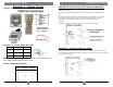
MAGENTA MULTIVIEW™ SERIES CHAPTER 3: SETUP & INSTALLATION. 2. Introduction 3. Setup and Installation 2.1 Overview 3.1 Cabling Considerations Magenta’s MultiView™ CAT5 Video System MultiView series extends VGA and audio signals over ordinary Category 5 cable. This manual covers the Magenta MultiView™ T4/T5 multi output CAT5 Video System Series transmitters. The T4/T5 transmitter is compatible with all MV and AK series of receivers.
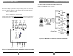
MAGENTA MULTIVIEW™ SERIES CHAPTER 3: Setup and Installation. 3.2.3 A TYPICAL MULTIVIEW T4 TRANSMITTER–RECEIVER APPLICATION Figure 3-2 shows an application in which a MultiView™ Series T4 Transmitter is linked to four MultiView™ Series Receivers. 3.2.2 CONNECTIONS ON THE TRANSMITTER The MultiView 450 T4/T5 four port transmitter is used when the same signal is distributed to multiple display devices. Set up and cabling are the same as the single port transmitter.
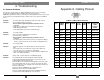
MAGENTA MULTIVIEW™ SERIES APPENDIX A: Cable Pinouts. 4. Troubleshooting Appendix A. Cabling Pinouts 4.1 Common Problems In most cases, nearly every issue with the MultiView™ Series can be resolved by checking the CAT5 termination and making sure that it’s pinned to the 568B wiring specification. However, there may be other problems that cause the system to not perform as it’s designed. Below are solutions to the most common installation errors.
MAGENTA MULTIVIEW™ SERIES APPENDIX B: Sync Termination. Appendix A. Cabling Pinouts Table A-2. T568B CAT5 pinout Appendix B: Setting Sync Signal Output termination: In some cases it may be necessary to change the 75 Ohm termination of the sync outputs on the MultiView 450 units. This can be accomplished by opening the unit and installing jumpers on the on the circuit board. The settings will disable/enable the 75 Ohm termination on individual units. i.e.