MultiView 250A Receiver Quick Reference & Setup Guide Magenta Research Magenta Research 934 Federal Road, Brookfield, CT 06804 USA (203) 740-0592 FAX (203) 740-0596 www.magenta-research.com 934 Federal Road, Brookfield, CT 06804 USA (203) 740-0592 FAX (203) 740-0596 www.magenta-research.
. FCC/IC RFI STATEMENTS, EU DECLARATION OF CONFORMITY FEDERAL COMMUNICATIONS COMMISSION AND INDUSTRY CANADA RADIO FREQUENCY INTERFERENCE STATEMENTS This equipment generates, uses, and can radiate radio-frequency energy, and if not installed and used properly, that is, in strict accordance with the manufacturer’s instructions, may cause interference to radio communication.
CHAPTER 1: Specifications . 1.Specifications Cable Required: Category 5, 5e, 6 shielded or unshielded twisted pair Compliance: CE; FCC Class A, IC Class/class A Video Support: to UXGA (1600x1200 @ 70Hz), RGBHV, RGB, Composite, SVideo, Component Video modes Maximum Resolution and Refresh Rate: At 250 ft.
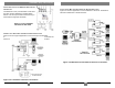
. CHAPTER 3: SETUP & INSTALLATION 3. Setup and Installation 3.1 Cabling Considerations • We recommend mounting and connecting all cabling to the MultiView™ Series components before applying power. • Make sure that the CAT5 cable you intend to use has been tested to comply with the T568B wiring specification (See Appendix A). 3.2.2 CONNECTIONS ON THE SINGLE-PORT VGA/AUDIO TRANSMITTER The single-port units with audio support video and audio signals over CAT5 cable.
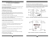
. CHAPTER 3: Setup and Installation 3.2.3 CONNECTIONS ON THE VGA/AUDIO MULTIVIEW T4 TRANSMITTERS The MultiView T4 four-port transmitter is used when the same signal is distributed to multiple display devices. You set it up and cable it the same as you would with the single-port transmitter. 3.2.5 A TYPICAL MULTIVIEW T4 TRANSMITTER–RECEIVER APPLICATION Figure 3-5 shows an application in which a MultiView™ Series T4 Transmitter is linked to four MultiView™ Series Receivers. Figure 3-3.
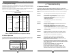
. CHAPTER 3: Setup and Installation 4. Troubleshooting 3.3 Configuration Settings The MultiView™ 250A receiver is configurable for various video and audio modes. Note that a compatible transmitter unit must be used at the source end. Reference the appropriate transmitter user guide or call for technical assistance. A dipswitch on the receiver unit is used to set the video and audio configuration mode.
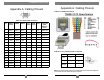
. APPENDIX A: Cabling Pinouts Appendix A. Cabling Pinouts Appendix A. Cabling Pinouts Table A-2. T568B CAT5 pinout Table A-1. HD15 video connector.