
User Manual
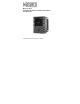
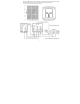
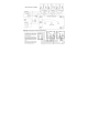
Table Of Contents

6
This detector helps monitor for the presence and concentration level of a certain specified airborne gas. Misuse may produce an
inaccurate reading, which means that higher levels of the gas being monitored may be present and could result in overexposure and
cause sickness or death. For proper use, see supervisor or User Instructions, or call Technical Service at 1-877-367-7891.
Location
A GD-12 mounting height is dependent upon the target gas.
If the target gas is lighter than air; methane (NG) or Hydrogen (H2), mount the GD-12 high on a wall or column (about one foot
down from the ceiling) in a central area where air movement is generally good.
If the target gas is heavier than air; propane (LP), mount the GD-12 low on a wall or column (about one foot above the floor) in
a central area where air movement is generally good.
The unit, on average, can cover about 900 sq. ft. (84 sq. meters). The coverage depends on air movement within the room or facility.
Extra detectors may be needed near any areas where people work or where the air is stagnant. Do NOT mount the GD-12 where the
normal ambient temperature is below below 0°F or exceeds 125°F (below -18C or above 52C).
High voltage terminals (100-240VAC) are located within this detector, presenting a hazard to service technicians. Only qualified
technicians should open the detector case and service the internal circuits. Ensure power is removed from the detector prior to
servicing the unit. Failure to do so may result in sickness or death.
General Wiring Information
With the exception of the safety ground, all field wiring is completed via modular connectors (provided). After wiring, simply plug the
modular connectors into the matching connectors on the back side of the detector.
Mains Power Connection
Mains connections should be done in accordance with National and Local Electrical Codes. Only qualified personnel should connect
Mains power to any device. Macurco recommends a minimum wire size of AWG18 and the wire insulator must be rated for 140°F
(60°C) service. The modular connector will accept wire from 12 to 24 AWG.
The safety ground wire should be secured to the ground screw of the metal electrical box. Tighten the screw and make sure the wire is
snug. Ensure that the wire cannot be pulled out from under the screw.
The Line (L) and Neutral (N) wires should be stripped 1/4 in. (6.5 mm), insert the wire into the ”L” and “N” wire positions of the modular
Fan/Power connector and tighten the screw clamp. Ensure that the wire cannot be easily pulled from the connector. Plug the modular
connection into the Fan/Power connection and ensure that it latches into the header properly.
Fan Relay Connection
All of the SPDT Fan relay terminals are available at the Fan/Power modular connector. Each Fan relay terminal normally open,
common and normally closed (NO, COM and NC) can accommodate a wire size 12 to 24 AWG. To install the wiring for the relays,
disconnect the connector from the header. Strip the insulation of each wire back approximately 1/4 in. (6.5 mm), insert the bare wire
! WARNING
! WARNING