
User Manual
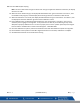


Table Of Contents
- Macurco_CX-xx_Operation_Manual(Rev-1.1)_Eng.pdf
- 1 General Safety Information
- 2 Use Instructions and Limitations
- 3 Installation and Operating Instructions
- 4 Operations
- 4.1 Power up
- 4.2 Display turned “On”
- 4.3 Display turned “Off”
- 4.4 4-20mA Loop
- 4.5 Configuration “CON”
- 4.5.1 Default – Factory Settings
- 4.5.2 Select Default Configuration – “dEF”
- 4.5.3 Select Power-Up Test Setting – “PUt”
- 4.5.4 Select Display Configuration – “dSP”
- 4.5.5 Select Buzzer Configuration – “bUZ”
- 4.5.6 Select Alarm Relay Setting for CO – “ArS.C”
- 4.5.7 Select Alarm Relay Setting for NO2 – “ArS.n”
- 4.5.8 Select Alarm Relay Configuration – “Arc”
- 4.5.9 Select Fan Relay Setting for CO – “FrS.C”
- 4.5.10 Select Fan Relay Setting for NO2 – “FrS.n”
- 4.5.11 Select Fan Relay Delay Setting – “Frd”
- 4.5.12 Select Fan Relay Minimum Runtime Setting – “Frr”
- 4.5.13 Select Fan Relay Latching Setting – “FrL”
- 4.5.14 Select Trouble Fan Setting – “tFS”
- 4.5.15 Select 4-20mA Output Setting – “420”
- 4.5.16 Select 4-20mA Mode – “420.n”
- 4.5.17 Select Calibration Period for CO Sensor – “CAL.C”
- 4.5.18 Select Calibration Period for NO2 Sensor – “CAL.n”
- 5 Troubleshooting
- 6 Maintenance
- 7 Testing
- 8 Appendix A – Table of Figures
- 9 Appendix B – Menu Structure
- 10 Macurco Gas Detection Product limited warranty
- Blank Page
- Macurco_CX-xx_Operation_Manual(Rev-1.1)_FR-CA.pdf
- 1 Informations générales de sécurité
- 2 Instructions et limites d'utilisation
- 3 Instructions d'installation et de fonctionnement
- 4 Fonctionnement
- 4.1 Mise sous tension
- 4.2 Affichage activé
- 4.3 Affichage désactivé
- 4.4 Boucle de courant 4-20 mA
- 4.5 Configuration « CON »
- 4.5.1 Par défaut - Paramètres d'usine
- 4.5.2 Sélectionner la configuration par défaut – « dEF »
- 4.5.3 Sélectionner le paramètre de test de mise sous tension – « Put »
- 4.5.4 Sélectionner Configuration de l'affichage – « dSP »
- 4.5.5 Sélectionner la configuration de l’avertisseur sonore – « bUZ »
- 4.5.6 Sélectionner Réglage du relais d'alarme pour CO – « ArS.C »
- 4.5.7 Sélectionner Réglage du relais d'alarme pour NO2 – « ArS.n »
- 4.5.8 Sélectionner Configuration du relais d'alarme – « Arc »
- 4.5.9 Sélectionner Réglage du relais de ventilateur pour CO – « FrS.C »
- 4.5.10 Sélectionner Réglage du relais de ventilateur pour NO2 – « FrS.n »
- 4.5.11 Sélectionner Réglage du délai du relais de ventilateur – « Frd »
- 4.5.12 Sélectionner Réglage de la durée de fonctionnement minimale du relais de ventilateur – « Frr »
- 4.5.13 Sélectionner Réglage de verrouillage du relais de ventilateur – « FrL »
- 4.5.14 Sélectionner Réglage du ventilateur en cas de défaillance - « tFS »
- 4.5.15 Sélectionner Réglage de la sortie 4-20 mA – « 420 »
- 4.5.16 Sélectionner le mode 4-20 mA – « 420.n »
- 4.5.17 Sélectionner Période d'étalonnage pour le capteur de CO - « CAL.C »
- 4.5.18 Sélectionner Période d'étalonnage pour le capteur de NO2 – « CAL.n »
- 5 Dépannage
- 6 Entretien
- 7 Tests
- 8 Annexe A – Tableau des figures
- 9 Annexe B – Structure du menu
- 10 Garantie limitée des détecteurs de gaz Macurco
- Blank Page
- Macurco_CX-xx_Operation_Manual(Rev-1.1)_SPA.pdf
- 1 Información general de seguridad
- 2 Instrucciones de uso y limitaciones
- 3 Instrucciones de instalación y de operación
- 4 Operaciones
- 4.1 Encendido
- 4.2 Pantalla "Enc." ("On")
- 4.3 Pantalla "Apag." ("Off")
- 4.4 Lazo de 4-20 mA
- 4.5 "Configuración" ("CON")
- 4.5.1 Configuración predeterminada de fábrica
- 4.5.2 Selección de la "Configuración predeterminada" ("dEF")
- 4.5.3 Selección de la opción de "Prueba de encendido" ("PUt")
- 4.5.4 Selección de la "Configuración de pantalla" ("dSP")
- 4.5.5 Selección de la "Configuración de zumbador" ("bUZ")
- 4.5.6 Selección del "Valor de ajuste del relé de alarma para CO" ("ArS.C")
- 4.5.7 Selección del "Valor de ajuste del relé de alarma para NO2" ("ArS.n")
- 4.5.8 Selección de la "Configuración de relé de alarma" ("Arc")
- 4.5.9 Selección del "Valor de ajuste del relé de ventilador para CO" ("FrS.C")
- 4.5.10 Selección del "Valor de ajuste del relé de ventilador para NO2" ("FrS.n")
- 4.5.11 Selección del valor de ajuste del "Retardo del relé de ventilador" ("Frd")
- 4.5.12 Selección del valor de ajuste del "Tiempo de funcionamiento mínimo del relé de ventilador" ("Frr")
- 4.5.13 Selección de la opción de "Enclavamiento del relé de ventilador" ("FrL")
- 4.5.14 Selección de la "Opción de ventilador en caso de problema" ("tFS")
- 4.5.15 Selección de la opción de "Salida de 4-20 mA" ("420")
- 4.5.16 Selección del "Modo de 4-20 mA" ("420.n")
- 4.5.17 Selección del "Período de calibración para el sensor de CO" ("CAL.C")
- 4.5.18 Selección del "Período de calibración para el sensor de NO2" ("CAL.n")
- 5 Localización de fallas
- 6 Mantenimiento
- 7 Pruebas
- 8 Apéndice A: Tabla de figuras
- 9 Apéndice B: Estructura de menús
- 10 Garantía limitada de los productos de detección de gas Macurco
- Blank Page

Macurco CX-xx Manual (Rev-1.0) Eng
REV – 1.1 [34-2900-0512-0 ] 40 | Page
Note: The sensor will look for the gas for 90 seconds. If no gas is applied or detected in that time, the display
will return to “CAL”.
10. When the sensor detects the gas, the display will flash between the “gas concentration” and “SPn.n”, then
the calibration will progress, and the display will show the gas level for a maximum of 165 seconds.
11. When the calibration is successful, the display will flash between the “gas concentration” and “PAS.n”, then
the display will show the calibration gas level and the calibration is done.
12. If the calibration fails, the display will flash between the “gas concentration” and “FAil.n”. If this occurs,
check the pressure gauge on the regulator. If the pressure is less than 25 psi the flow of gas may not be
adequate to properly calibrate the unit. If there is proper pressure in the cylinder repeat steps 4 through 6.
If the unit fails to calibrate twice contact Technical Support : 1-844-325-3050.
13. Once the calibration has passed, remove the calibration hood and disassemble the cylinder and regulator.
14. Re-assemble the CX-xx (make sure the LED is aligned with the front case hole). Calibration is complete.
15. See Calibration Flowchart on the inside of the housing.