
User Manual
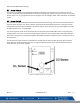


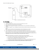


Table Of Contents
- Macurco_CX-xx_Operation_Manual(Rev-1.1)_Eng.pdf
- 1 General Safety Information
- 2 Use Instructions and Limitations
- 3 Installation and Operating Instructions
- 4 Operations
- 4.1 Power up
- 4.2 Display turned “On”
- 4.3 Display turned “Off”
- 4.4 4-20mA Loop
- 4.5 Configuration “CON”
- 4.5.1 Default – Factory Settings
- 4.5.2 Select Default Configuration – “dEF”
- 4.5.3 Select Power-Up Test Setting – “PUt”
- 4.5.4 Select Display Configuration – “dSP”
- 4.5.5 Select Buzzer Configuration – “bUZ”
- 4.5.6 Select Alarm Relay Setting for CO – “ArS.C”
- 4.5.7 Select Alarm Relay Setting for NO2 – “ArS.n”
- 4.5.8 Select Alarm Relay Configuration – “Arc”
- 4.5.9 Select Fan Relay Setting for CO – “FrS.C”
- 4.5.10 Select Fan Relay Setting for NO2 – “FrS.n”
- 4.5.11 Select Fan Relay Delay Setting – “Frd”
- 4.5.12 Select Fan Relay Minimum Runtime Setting – “Frr”
- 4.5.13 Select Fan Relay Latching Setting – “FrL”
- 4.5.14 Select Trouble Fan Setting – “tFS”
- 4.5.15 Select 4-20mA Output Setting – “420”
- 4.5.16 Select 4-20mA Mode – “420.n”
- 4.5.17 Select Calibration Period for CO Sensor – “CAL.C”
- 4.5.18 Select Calibration Period for NO2 Sensor – “CAL.n”
- 5 Troubleshooting
- 6 Maintenance
- 7 Testing
- 8 Appendix A – Table of Figures
- 9 Appendix B – Menu Structure
- 10 Macurco Gas Detection Product limited warranty
- Blank Page
- Macurco_CX-xx_Operation_Manual(Rev-1.1)_FR-CA.pdf
- 1 Informations générales de sécurité
- 2 Instructions et limites d'utilisation
- 3 Instructions d'installation et de fonctionnement
- 4 Fonctionnement
- 4.1 Mise sous tension
- 4.2 Affichage activé
- 4.3 Affichage désactivé
- 4.4 Boucle de courant 4-20 mA
- 4.5 Configuration « CON »
- 4.5.1 Par défaut - Paramètres d'usine
- 4.5.2 Sélectionner la configuration par défaut – « dEF »
- 4.5.3 Sélectionner le paramètre de test de mise sous tension – « Put »
- 4.5.4 Sélectionner Configuration de l'affichage – « dSP »
- 4.5.5 Sélectionner la configuration de l’avertisseur sonore – « bUZ »
- 4.5.6 Sélectionner Réglage du relais d'alarme pour CO – « ArS.C »
- 4.5.7 Sélectionner Réglage du relais d'alarme pour NO2 – « ArS.n »
- 4.5.8 Sélectionner Configuration du relais d'alarme – « Arc »
- 4.5.9 Sélectionner Réglage du relais de ventilateur pour CO – « FrS.C »
- 4.5.10 Sélectionner Réglage du relais de ventilateur pour NO2 – « FrS.n »
- 4.5.11 Sélectionner Réglage du délai du relais de ventilateur – « Frd »
- 4.5.12 Sélectionner Réglage de la durée de fonctionnement minimale du relais de ventilateur – « Frr »
- 4.5.13 Sélectionner Réglage de verrouillage du relais de ventilateur – « FrL »
- 4.5.14 Sélectionner Réglage du ventilateur en cas de défaillance - « tFS »
- 4.5.15 Sélectionner Réglage de la sortie 4-20 mA – « 420 »
- 4.5.16 Sélectionner le mode 4-20 mA – « 420.n »
- 4.5.17 Sélectionner Période d'étalonnage pour le capteur de CO - « CAL.C »
- 4.5.18 Sélectionner Période d'étalonnage pour le capteur de NO2 – « CAL.n »
- 5 Dépannage
- 6 Entretien
- 7 Tests
- 8 Annexe A – Tableau des figures
- 9 Annexe B – Structure du menu
- 10 Garantie limitée des détecteurs de gaz Macurco
- Blank Page
- Macurco_CX-xx_Operation_Manual(Rev-1.1)_SPA.pdf
- 1 Información general de seguridad
- 2 Instrucciones de uso y limitaciones
- 3 Instrucciones de instalación y de operación
- 4 Operaciones
- 4.1 Encendido
- 4.2 Pantalla "Enc." ("On")
- 4.3 Pantalla "Apag." ("Off")
- 4.4 Lazo de 4-20 mA
- 4.5 "Configuración" ("CON")
- 4.5.1 Configuración predeterminada de fábrica
- 4.5.2 Selección de la "Configuración predeterminada" ("dEF")
- 4.5.3 Selección de la opción de "Prueba de encendido" ("PUt")
- 4.5.4 Selección de la "Configuración de pantalla" ("dSP")
- 4.5.5 Selección de la "Configuración de zumbador" ("bUZ")
- 4.5.6 Selección del "Valor de ajuste del relé de alarma para CO" ("ArS.C")
- 4.5.7 Selección del "Valor de ajuste del relé de alarma para NO2" ("ArS.n")
- 4.5.8 Selección de la "Configuración de relé de alarma" ("Arc")
- 4.5.9 Selección del "Valor de ajuste del relé de ventilador para CO" ("FrS.C")
- 4.5.10 Selección del "Valor de ajuste del relé de ventilador para NO2" ("FrS.n")
- 4.5.11 Selección del valor de ajuste del "Retardo del relé de ventilador" ("Frd")
- 4.5.12 Selección del valor de ajuste del "Tiempo de funcionamiento mínimo del relé de ventilador" ("Frr")
- 4.5.13 Selección de la opción de "Enclavamiento del relé de ventilador" ("FrL")
- 4.5.14 Selección de la "Opción de ventilador en caso de problema" ("tFS")
- 4.5.15 Selección de la opción de "Salida de 4-20 mA" ("420")
- 4.5.16 Selección del "Modo de 4-20 mA" ("420.n")
- 4.5.17 Selección del "Período de calibración para el sensor de CO" ("CAL.C")
- 4.5.18 Selección del "Período de calibración para el sensor de NO2" ("CAL.n")
- 5 Localización de fallas
- 6 Mantenimiento
- 7 Pruebas
- 8 Apéndice A: Tabla de figuras
- 9 Apéndice B: Estructura de menús
- 10 Garantía limitada de los productos de detección de gas Macurco
- Blank Page

Macurco CX-xx Manual (Rev-1.0) Eng
REV – 1.1 [34-2900-0512-0 ] 38 | Page
5. With the CX-xx cover on, aim the nozzle of the aerosol can into the sensor grate area (under DO NOT PAINT)
and press for 2 to 3 seconds.
6. Wait for a few seconds. The digital display should climb indicating the increased gas concentration at the
sensor confirming a pass of the quick test.
Note: If the Display does not change within 10 seconds, there are four possibilities:
a. Gas cylinder is empty, replace the gas cylinder.
b. Unit needs to be re-calibrated (go through the Field Calibration Procedure and re-test).
c. Detector needs servicing (return unit to factory for servicing).
7. Wait for the display to return to 0 ppm and configure options to desired settings.
7.4 Field Calibration Procedure
NOTE: For optimum calibration results the unit should be in clean air and be in a low ambient air flow.
CX-xx has “CAL” top level menu that can be used to perform a field calibration. “tSC.C”, “tSC.n”, “000.C”, “000.n”,
“Spn.C”, “Spn.n”, and “End” are sub-menus within the “CAL” menu.
• “tSC.C” and “tSC.n” are read only and represent the time since last calibration for each sensor. Select either
sub-menu and it will display a value in the format YY.MM. “MM” are for months and “YY” for year. E.g. if the
value is 00.05 then it has been zero years and 5 months since the unit was last calibrated.
• “000.C”and “000.n” are used to start a zero calibration for each respective sensor. Follow the procedures
below to perform a zero calibration.
• “Spn.C” and “Spn.n” are used to start a span calibration for each respective sensor. Follow the procedures
below to perform a span calibration.
• “End” sub-menu is used to exit the “CAL” menu.
A complete field calibration requires a zero calibration and a span calibration. A zero calibration provides a reference
value by exposing the sensor to clean air. A span calibration exposes the sensor to a known concentration of test
gas.
7.4.1 Zero Calibration for CO Sensor
To perform a zero calibration for the CO sensor,
1. Press Next 3 times to get to the “CAL” menu
2. Press Enter. The display will show “tSC.C”.
3. Press Next 2 times to get to “000.C” and Press Enter.
4. The display will flash between ‘000.C’ and the current CO reading i.e. “C 0”.
5. After approximately 45 seconds, the zero calibration is complete. For a successful zeroing, the display will
flash between “PAS.C” and the current CO reading “C 0”. If the zero calibration fails, the display will show
FAil.C.
6. The green LED blinks during the process. When the green LED returns to solid, the calibration is complete.
7.4.2 Zero Calibration for NO
2
Sensor
To perform a zero calibration for the NO
2
sensor,
1. Press Next 3 times to get to the “CAL” menu
2. Press Enter. The display will show “tSC.C”.
3. Press Next 3 times.
4. The display will show “000.n”. Press Enter.