
User Manual
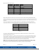
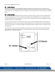

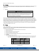


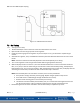


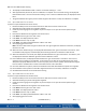
Table Of Contents
- Macurco_CX-xx_Operation_Manual(Rev-1.1)_Eng.pdf
- 1 General Safety Information
- 2 Use Instructions and Limitations
- 3 Installation and Operating Instructions
- 4 Operations
- 4.1 Power up
- 4.2 Display turned “On”
- 4.3 Display turned “Off”
- 4.4 4-20mA Loop
- 4.5 Configuration “CON”
- 4.5.1 Default – Factory Settings
- 4.5.2 Select Default Configuration – “dEF”
- 4.5.3 Select Power-Up Test Setting – “PUt”
- 4.5.4 Select Display Configuration – “dSP”
- 4.5.5 Select Buzzer Configuration – “bUZ”
- 4.5.6 Select Alarm Relay Setting for CO – “ArS.C”
- 4.5.7 Select Alarm Relay Setting for NO2 – “ArS.n”
- 4.5.8 Select Alarm Relay Configuration – “Arc”
- 4.5.9 Select Fan Relay Setting for CO – “FrS.C”
- 4.5.10 Select Fan Relay Setting for NO2 – “FrS.n”
- 4.5.11 Select Fan Relay Delay Setting – “Frd”
- 4.5.12 Select Fan Relay Minimum Runtime Setting – “Frr”
- 4.5.13 Select Fan Relay Latching Setting – “FrL”
- 4.5.14 Select Trouble Fan Setting – “tFS”
- 4.5.15 Select 4-20mA Output Setting – “420”
- 4.5.16 Select 4-20mA Mode – “420.n”
- 4.5.17 Select Calibration Period for CO Sensor – “CAL.C”
- 4.5.18 Select Calibration Period for NO2 Sensor – “CAL.n”
- 5 Troubleshooting
- 6 Maintenance
- 7 Testing
- 8 Appendix A – Table of Figures
- 9 Appendix B – Menu Structure
- 10 Macurco Gas Detection Product limited warranty
- Blank Page
- Macurco_CX-xx_Operation_Manual(Rev-1.1)_FR-CA.pdf
- 1 Informations générales de sécurité
- 2 Instructions et limites d'utilisation
- 3 Instructions d'installation et de fonctionnement
- 4 Fonctionnement
- 4.1 Mise sous tension
- 4.2 Affichage activé
- 4.3 Affichage désactivé
- 4.4 Boucle de courant 4-20 mA
- 4.5 Configuration « CON »
- 4.5.1 Par défaut - Paramètres d'usine
- 4.5.2 Sélectionner la configuration par défaut – « dEF »
- 4.5.3 Sélectionner le paramètre de test de mise sous tension – « Put »
- 4.5.4 Sélectionner Configuration de l'affichage – « dSP »
- 4.5.5 Sélectionner la configuration de l’avertisseur sonore – « bUZ »
- 4.5.6 Sélectionner Réglage du relais d'alarme pour CO – « ArS.C »
- 4.5.7 Sélectionner Réglage du relais d'alarme pour NO2 – « ArS.n »
- 4.5.8 Sélectionner Configuration du relais d'alarme – « Arc »
- 4.5.9 Sélectionner Réglage du relais de ventilateur pour CO – « FrS.C »
- 4.5.10 Sélectionner Réglage du relais de ventilateur pour NO2 – « FrS.n »
- 4.5.11 Sélectionner Réglage du délai du relais de ventilateur – « Frd »
- 4.5.12 Sélectionner Réglage de la durée de fonctionnement minimale du relais de ventilateur – « Frr »
- 4.5.13 Sélectionner Réglage de verrouillage du relais de ventilateur – « FrL »
- 4.5.14 Sélectionner Réglage du ventilateur en cas de défaillance - « tFS »
- 4.5.15 Sélectionner Réglage de la sortie 4-20 mA – « 420 »
- 4.5.16 Sélectionner le mode 4-20 mA – « 420.n »
- 4.5.17 Sélectionner Période d'étalonnage pour le capteur de CO - « CAL.C »
- 4.5.18 Sélectionner Période d'étalonnage pour le capteur de NO2 – « CAL.n »
- 5 Dépannage
- 6 Entretien
- 7 Tests
- 8 Annexe A – Tableau des figures
- 9 Annexe B – Structure du menu
- 10 Garantie limitée des détecteurs de gaz Macurco
- Blank Page
- Macurco_CX-xx_Operation_Manual(Rev-1.1)_SPA.pdf
- 1 Información general de seguridad
- 2 Instrucciones de uso y limitaciones
- 3 Instrucciones de instalación y de operación
- 4 Operaciones
- 4.1 Encendido
- 4.2 Pantalla "Enc." ("On")
- 4.3 Pantalla "Apag." ("Off")
- 4.4 Lazo de 4-20 mA
- 4.5 "Configuración" ("CON")
- 4.5.1 Configuración predeterminada de fábrica
- 4.5.2 Selección de la "Configuración predeterminada" ("dEF")
- 4.5.3 Selección de la opción de "Prueba de encendido" ("PUt")
- 4.5.4 Selección de la "Configuración de pantalla" ("dSP")
- 4.5.5 Selección de la "Configuración de zumbador" ("bUZ")
- 4.5.6 Selección del "Valor de ajuste del relé de alarma para CO" ("ArS.C")
- 4.5.7 Selección del "Valor de ajuste del relé de alarma para NO2" ("ArS.n")
- 4.5.8 Selección de la "Configuración de relé de alarma" ("Arc")
- 4.5.9 Selección del "Valor de ajuste del relé de ventilador para CO" ("FrS.C")
- 4.5.10 Selección del "Valor de ajuste del relé de ventilador para NO2" ("FrS.n")
- 4.5.11 Selección del valor de ajuste del "Retardo del relé de ventilador" ("Frd")
- 4.5.12 Selección del valor de ajuste del "Tiempo de funcionamiento mínimo del relé de ventilador" ("Frr")
- 4.5.13 Selección de la opción de "Enclavamiento del relé de ventilador" ("FrL")
- 4.5.14 Selección de la "Opción de ventilador en caso de problema" ("tFS")
- 4.5.15 Selección de la opción de "Salida de 4-20 mA" ("420")
- 4.5.16 Selección del "Modo de 4-20 mA" ("420.n")
- 4.5.17 Selección del "Período de calibración para el sensor de CO" ("CAL.C")
- 4.5.18 Selección del "Período de calibración para el sensor de NO2" ("CAL.n")
- 5 Localización de fallas
- 6 Mantenimiento
- 7 Pruebas
- 8 Apéndice A: Tabla de figuras
- 9 Apéndice B: Estructura de menús
- 10 Garantía limitada de los productos de detección de gas Macurco
- Blank Page

Macurco CX-xx Manual (Rev-1.0) Eng
REV – 1.1 [34-2900-0512-0 ] 34 | Page
Table 7-1
b. At the end of the test cycle, the fan & alarm relay will be in standby mode and the 4-20 mA output
will return to 4 mA (in clean air).
8. When testing is complete, reassemble the unit.
7.1.2 Manual Operation Test
This option gives the user the opportunity to manually initiate an individual test for each relay, the analog output
and the sensor response to gas.
To initiate a manual operation test,
1. From normal operation mode press Next 2 times to get to Test Mode (tSt).
2. Press Enter once to get into the Test Menu.
3. Press Next to scroll through the six test options.
Test
Description
Test Length
Display
bUZ
Buzzer Test
3 seconds
Flashes “bUZ”
Art
Alarm Relay Test
5 seconds
Flashes “Art”
Frt
Fan Relay Test
60 seconds
Flashes “Frt”
42t.C
4-20 mA Test for CO
130 seconds
Flashes “42t.C”
42t.n
4-20 mA Test for NO
2
130 seconds
Flashes “42t.n”
gtS Gas Test 180 seconds
Flashes in a sequence of gtS, CO reading (indicated by C in
the beginning) and NO2 reading (indicated by n in the
beginning). No output to the panel during the gas test.
Table 7-2
4. Press Enter to initiate the selected test. Note that if the relay or 4–20 mA output has been disabled, the test
selection will not be displayed in the test menu.
5. Once the test is complete, the display will return to steady display. To exit the test menu, press the Next
button until “End” is displayed. Then, press Enter to return to normal mode.
7.2 Calibration and Test Kits
WARNING
The following steps must be performed when conducting a calibration verification test
(bump test) to ensure proper performance of the monitor. Failure to do so may
adversely affect product performance.
• When performing a calibration verification test (bump test) only use certified
calibration gas at the required concentration level.
• Do not test with expired calibration gas.
• Do not cover or obstruct display or visual alarm cover.
• Ensure sensor inlets are unobstructed and are free of debris
Failure to follow instructions outlined in this user manual can result in sickness or
death.