
User Manual
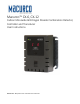


Table Of Contents
- Macurco_CX-xx_Operation_Manual(Rev-1.1)_Eng.pdf
- 1 General Safety Information
- 2 Use Instructions and Limitations
- 3 Installation and Operating Instructions
- 4 Operations
- 4.1 Power up
- 4.2 Display turned “On”
- 4.3 Display turned “Off”
- 4.4 4-20mA Loop
- 4.5 Configuration “CON”
- 4.5.1 Default – Factory Settings
- 4.5.2 Select Default Configuration – “dEF”
- 4.5.3 Select Power-Up Test Setting – “PUt”
- 4.5.4 Select Display Configuration – “dSP”
- 4.5.5 Select Buzzer Configuration – “bUZ”
- 4.5.6 Select Alarm Relay Setting for CO – “ArS.C”
- 4.5.7 Select Alarm Relay Setting for NO2 – “ArS.n”
- 4.5.8 Select Alarm Relay Configuration – “Arc”
- 4.5.9 Select Fan Relay Setting for CO – “FrS.C”
- 4.5.10 Select Fan Relay Setting for NO2 – “FrS.n”
- 4.5.11 Select Fan Relay Delay Setting – “Frd”
- 4.5.12 Select Fan Relay Minimum Runtime Setting – “Frr”
- 4.5.13 Select Fan Relay Latching Setting – “FrL”
- 4.5.14 Select Trouble Fan Setting – “tFS”
- 4.5.15 Select 4-20mA Output Setting – “420”
- 4.5.16 Select 4-20mA Mode – “420.n”
- 4.5.17 Select Calibration Period for CO Sensor – “CAL.C”
- 4.5.18 Select Calibration Period for NO2 Sensor – “CAL.n”
- 5 Troubleshooting
- 6 Maintenance
- 7 Testing
- 8 Appendix A – Table of Figures
- 9 Appendix B – Menu Structure
- 10 Macurco Gas Detection Product limited warranty
- Blank Page
- Macurco_CX-xx_Operation_Manual(Rev-1.1)_FR-CA.pdf
- 1 Informations générales de sécurité
- 2 Instructions et limites d'utilisation
- 3 Instructions d'installation et de fonctionnement
- 4 Fonctionnement
- 4.1 Mise sous tension
- 4.2 Affichage activé
- 4.3 Affichage désactivé
- 4.4 Boucle de courant 4-20 mA
- 4.5 Configuration « CON »
- 4.5.1 Par défaut - Paramètres d'usine
- 4.5.2 Sélectionner la configuration par défaut – « dEF »
- 4.5.3 Sélectionner le paramètre de test de mise sous tension – « Put »
- 4.5.4 Sélectionner Configuration de l'affichage – « dSP »
- 4.5.5 Sélectionner la configuration de l’avertisseur sonore – « bUZ »
- 4.5.6 Sélectionner Réglage du relais d'alarme pour CO – « ArS.C »
- 4.5.7 Sélectionner Réglage du relais d'alarme pour NO2 – « ArS.n »
- 4.5.8 Sélectionner Configuration du relais d'alarme – « Arc »
- 4.5.9 Sélectionner Réglage du relais de ventilateur pour CO – « FrS.C »
- 4.5.10 Sélectionner Réglage du relais de ventilateur pour NO2 – « FrS.n »
- 4.5.11 Sélectionner Réglage du délai du relais de ventilateur – « Frd »
- 4.5.12 Sélectionner Réglage de la durée de fonctionnement minimale du relais de ventilateur – « Frr »
- 4.5.13 Sélectionner Réglage de verrouillage du relais de ventilateur – « FrL »
- 4.5.14 Sélectionner Réglage du ventilateur en cas de défaillance - « tFS »
- 4.5.15 Sélectionner Réglage de la sortie 4-20 mA – « 420 »
- 4.5.16 Sélectionner le mode 4-20 mA – « 420.n »
- 4.5.17 Sélectionner Période d'étalonnage pour le capteur de CO - « CAL.C »
- 4.5.18 Sélectionner Période d'étalonnage pour le capteur de NO2 – « CAL.n »
- 5 Dépannage
- 6 Entretien
- 7 Tests
- 8 Annexe A – Tableau des figures
- 9 Annexe B – Structure du menu
- 10 Garantie limitée des détecteurs de gaz Macurco
- Blank Page
- Macurco_CX-xx_Operation_Manual(Rev-1.1)_SPA.pdf
- 1 Información general de seguridad
- 2 Instrucciones de uso y limitaciones
- 3 Instrucciones de instalación y de operación
- 4 Operaciones
- 4.1 Encendido
- 4.2 Pantalla "Enc." ("On")
- 4.3 Pantalla "Apag." ("Off")
- 4.4 Lazo de 4-20 mA
- 4.5 "Configuración" ("CON")
- 4.5.1 Configuración predeterminada de fábrica
- 4.5.2 Selección de la "Configuración predeterminada" ("dEF")
- 4.5.3 Selección de la opción de "Prueba de encendido" ("PUt")
- 4.5.4 Selección de la "Configuración de pantalla" ("dSP")
- 4.5.5 Selección de la "Configuración de zumbador" ("bUZ")
- 4.5.6 Selección del "Valor de ajuste del relé de alarma para CO" ("ArS.C")
- 4.5.7 Selección del "Valor de ajuste del relé de alarma para NO2" ("ArS.n")
- 4.5.8 Selección de la "Configuración de relé de alarma" ("Arc")
- 4.5.9 Selección del "Valor de ajuste del relé de ventilador para CO" ("FrS.C")
- 4.5.10 Selección del "Valor de ajuste del relé de ventilador para NO2" ("FrS.n")
- 4.5.11 Selección del valor de ajuste del "Retardo del relé de ventilador" ("Frd")
- 4.5.12 Selección del valor de ajuste del "Tiempo de funcionamiento mínimo del relé de ventilador" ("Frr")
- 4.5.13 Selección de la opción de "Enclavamiento del relé de ventilador" ("FrL")
- 4.5.14 Selección de la "Opción de ventilador en caso de problema" ("tFS")
- 4.5.15 Selección de la opción de "Salida de 4-20 mA" ("420")
- 4.5.16 Selección del "Modo de 4-20 mA" ("420.n")
- 4.5.17 Selección del "Período de calibración para el sensor de CO" ("CAL.C")
- 4.5.18 Selección del "Período de calibración para el sensor de NO2" ("CAL.n")
- 5 Localización de fallas
- 6 Mantenimiento
- 7 Pruebas
- 8 Apéndice A: Tabla de figuras
- 9 Apéndice B: Estructura de menús
- 10 Garantía limitada de los productos de detección de gas Macurco
- Blank Page

Macurco CX-xx Manual (Rev-1.0) Eng
REV – 1.1 [34-2900-0512-0 ] 2 | Page
1 General Safety Information ...................................................................................................................................... 4
1.1 General Description .......................................................................................................................................... 4
1.2 List of warnings ................................................................................................................................................. 4
2 Use Instructions and Limitations .............................................................................................................................. 5
2.1 Use For .............................................................................................................................................................. 5
2.2 Do NOT use for ................................................................................................................................................. 6
2.3 Features ............................................................................................................................................................ 6
2.4 Specifications .................................................................................................................................................... 6
2.4.1 6-Series Low Voltage ................................................................................................................................ 7
2.4.2 12-Series Line Voltage .............................................................................................................................. 7
3 Installation and Operating Instructions .................................................................................................................... 7
3.1 Location ............................................................................................................................................................ 7
3.2 Installation ........................................................................................................................................................ 7
3.2.1 6-Series Low Voltage ................................................................................................................................ 7
3.2.2 12-Series Line Voltage ............................................................................................................................ 13
3.3 Terminal Connection ...................................................................................................................................... 18
3.3.1 6-Series Low Voltage .............................................................................................................................. 18
3.3.2 12-Series Line Voltage ............................................................................................................................ 19
4 Operations .............................................................................................................................................................. 20
4.1 Power up......................................................................................................................................................... 20
4.2 Display turned “On” ....................................................................................................................................... 20
4.3 Display turned “Off” ....................................................................................................................................... 21
4.4 4-20mA Loop .................................................................................................................................................. 22
4.5 Configuration “CON” ...................................................................................................................................... 22
4.5.1 Default – Factory Settings ...................................................................................................................... 23
4.5.2 Select Default Configuration – “dEF” ..................................................................................................... 23
4.5.3 Select Power-Up Test Setting – “PUt” .................................................................................................... 23
4.5.4 Select Display Configuration – “dSP” ...................................................................................................... 24
4.5.5 Select Buzzer Configuration – “bUZ” ...................................................................................................... 24
4.5.6 Select Alarm Relay Setting for CO – “ArS.C” ........................................................................................... 24
4.5.7 Select Alarm Relay Setting for NO2 – “ArS.n” ........................................................................................ 25
4.5.8 Select Alarm Relay Configuration – “Arc” .............................................................................................. 25
4.5.9 Select Fan Relay Setting for CO – “FrS.C” ............................................................................................... 25
4.5.10 Select Fan Relay Setting for NO2 – “FrS.n” ............................................................................................. 26
4.5.11 Select Fan Relay Delay Setting – “Frd” ................................................................................................... 26
4.5.12 Select Fan Relay Minimum Runtime Setting – “Frr”............................................................................... 26
4.5.13 Select Fan Relay Latching Setting – “FrL” ............................................................................................... 27
4.5.14 Select Trouble Fan Setting – “tFS” .......................................................................................................... 27
4.5.15 Select 4-20mA Output Setting – “420” ................................................................................................... 27
4.5.16 Select 4-20mA Mode – “420.n” .............................................................................................................. 28
4.5.17 Select Calibration Period for CO Sensor – “CAL.C” ................................................................................. 28
4.5.18 Select Calibration Period for NO
2
Sensor – “CAL.n” ............................................................................... 29
5 Troubleshooting ..................................................................................................................................................... 29