
User Manual

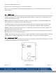


Table Of Contents
- Macurco_CX-xx_Operation_Manual(Rev-1.1)_Eng.pdf
- 1 General Safety Information
- 2 Use Instructions and Limitations
- 3 Installation and Operating Instructions
- 4 Operations
- 4.1 Power up
- 4.2 Display turned “On”
- 4.3 Display turned “Off”
- 4.4 4-20mA Loop
- 4.5 Configuration “CON”
- 4.5.1 Default – Factory Settings
- 4.5.2 Select Default Configuration – “dEF”
- 4.5.3 Select Power-Up Test Setting – “PUt”
- 4.5.4 Select Display Configuration – “dSP”
- 4.5.5 Select Buzzer Configuration – “bUZ”
- 4.5.6 Select Alarm Relay Setting for CO – “ArS.C”
- 4.5.7 Select Alarm Relay Setting for NO2 – “ArS.n”
- 4.5.8 Select Alarm Relay Configuration – “Arc”
- 4.5.9 Select Fan Relay Setting for CO – “FrS.C”
- 4.5.10 Select Fan Relay Setting for NO2 – “FrS.n”
- 4.5.11 Select Fan Relay Delay Setting – “Frd”
- 4.5.12 Select Fan Relay Minimum Runtime Setting – “Frr”
- 4.5.13 Select Fan Relay Latching Setting – “FrL”
- 4.5.14 Select Trouble Fan Setting – “tFS”
- 4.5.15 Select 4-20mA Output Setting – “420”
- 4.5.16 Select 4-20mA Mode – “420.n”
- 4.5.17 Select Calibration Period for CO Sensor – “CAL.C”
- 4.5.18 Select Calibration Period for NO2 Sensor – “CAL.n”
- 5 Troubleshooting
- 6 Maintenance
- 7 Testing
- 8 Appendix A – Table of Figures
- 9 Appendix B – Menu Structure
- 10 Macurco Gas Detection Product limited warranty
- Blank Page
- Macurco_CX-xx_Operation_Manual(Rev-1.1)_FR-CA.pdf
- 1 Informations générales de sécurité
- 2 Instructions et limites d'utilisation
- 3 Instructions d'installation et de fonctionnement
- 4 Fonctionnement
- 4.1 Mise sous tension
- 4.2 Affichage activé
- 4.3 Affichage désactivé
- 4.4 Boucle de courant 4-20 mA
- 4.5 Configuration « CON »
- 4.5.1 Par défaut - Paramètres d'usine
- 4.5.2 Sélectionner la configuration par défaut – « dEF »
- 4.5.3 Sélectionner le paramètre de test de mise sous tension – « Put »
- 4.5.4 Sélectionner Configuration de l'affichage – « dSP »
- 4.5.5 Sélectionner la configuration de l’avertisseur sonore – « bUZ »
- 4.5.6 Sélectionner Réglage du relais d'alarme pour CO – « ArS.C »
- 4.5.7 Sélectionner Réglage du relais d'alarme pour NO2 – « ArS.n »
- 4.5.8 Sélectionner Configuration du relais d'alarme – « Arc »
- 4.5.9 Sélectionner Réglage du relais de ventilateur pour CO – « FrS.C »
- 4.5.10 Sélectionner Réglage du relais de ventilateur pour NO2 – « FrS.n »
- 4.5.11 Sélectionner Réglage du délai du relais de ventilateur – « Frd »
- 4.5.12 Sélectionner Réglage de la durée de fonctionnement minimale du relais de ventilateur – « Frr »
- 4.5.13 Sélectionner Réglage de verrouillage du relais de ventilateur – « FrL »
- 4.5.14 Sélectionner Réglage du ventilateur en cas de défaillance - « tFS »
- 4.5.15 Sélectionner Réglage de la sortie 4-20 mA – « 420 »
- 4.5.16 Sélectionner le mode 4-20 mA – « 420.n »
- 4.5.17 Sélectionner Période d'étalonnage pour le capteur de CO - « CAL.C »
- 4.5.18 Sélectionner Période d'étalonnage pour le capteur de NO2 – « CAL.n »
- 5 Dépannage
- 6 Entretien
- 7 Tests
- 8 Annexe A – Tableau des figures
- 9 Annexe B – Structure du menu
- 10 Garantie limitée des détecteurs de gaz Macurco
- Blank Page
- Macurco_CX-xx_Operation_Manual(Rev-1.1)_SPA.pdf
- 1 Información general de seguridad
- 2 Instrucciones de uso y limitaciones
- 3 Instrucciones de instalación y de operación
- 4 Operaciones
- 4.1 Encendido
- 4.2 Pantalla "Enc." ("On")
- 4.3 Pantalla "Apag." ("Off")
- 4.4 Lazo de 4-20 mA
- 4.5 "Configuración" ("CON")
- 4.5.1 Configuración predeterminada de fábrica
- 4.5.2 Selección de la "Configuración predeterminada" ("dEF")
- 4.5.3 Selección de la opción de "Prueba de encendido" ("PUt")
- 4.5.4 Selección de la "Configuración de pantalla" ("dSP")
- 4.5.5 Selección de la "Configuración de zumbador" ("bUZ")
- 4.5.6 Selección del "Valor de ajuste del relé de alarma para CO" ("ArS.C")
- 4.5.7 Selección del "Valor de ajuste del relé de alarma para NO2" ("ArS.n")
- 4.5.8 Selección de la "Configuración de relé de alarma" ("Arc")
- 4.5.9 Selección del "Valor de ajuste del relé de ventilador para CO" ("FrS.C")
- 4.5.10 Selección del "Valor de ajuste del relé de ventilador para NO2" ("FrS.n")
- 4.5.11 Selección del valor de ajuste del "Retardo del relé de ventilador" ("Frd")
- 4.5.12 Selección del valor de ajuste del "Tiempo de funcionamiento mínimo del relé de ventilador" ("Frr")
- 4.5.13 Selección de la opción de "Enclavamiento del relé de ventilador" ("FrL")
- 4.5.14 Selección de la "Opción de ventilador en caso de problema" ("tFS")
- 4.5.15 Selección de la opción de "Salida de 4-20 mA" ("420")
- 4.5.16 Selección del "Modo de 4-20 mA" ("420.n")
- 4.5.17 Selección del "Período de calibración para el sensor de CO" ("CAL.C")
- 4.5.18 Selección del "Período de calibración para el sensor de NO2" ("CAL.n")
- 5 Localización de fallas
- 6 Mantenimiento
- 7 Pruebas
- 8 Apéndice A: Tabla de figuras
- 9 Apéndice B: Estructura de menús
- 10 Garantía limitada de los productos de detección de gas Macurco
- Blank Page

Macurco CX-xx Manual (Rev-1.0) Eng
REV – 1.1 [34-2900-0512-0 ] 21 | Page
Clean Air – The CX-xx will flash between the current concentration of CO ppm and the current concentration of NO
2
ppm. The CO reading will start with a “C” and the NO
2
reading will start with an “n”.
Fan Relay Level – When either the CO or NO
2
concentration reaches the Fan Relay setting and the Fan Run Delay
“Frd” period has elapsed, the display will flash between “FAn” and the current concentration of gases. The
sequence of display when the Fan Relay is activated is: “Fan”, CO (“CXXX”) reading, NO
2
reading (“n Y.Y”).
Alarm Relay Level – When either the CO or NO
2
concentration reaches the Alarm Relay setting, the display will flash
between “ALr” and the current concentration of gases. The sequence of display when the Alarm Relay is activated is:
“ALr”, CO Reading (“CXXX”), NO
2
reading (“n Y.Y”).The buzzer will sound indicating “Alarm” if the buzzer is turned
“On”.
Trouble – When the device is in a trouble state, the display will display the “t” Error code (t001 for example) and the
Alarm Relay will activate. If the Trouble Fan Setting is enabled, the Fan Relay will activate. See Section 5.1.2 Trouble
Codes and Section 4.5.14 Select Trouble Fan Setting – “tFS”
NOTE: Trouble states related to the CO and NO
2
sensors are represented by different “t” Error codes. So, if an error
exists for the CO or NO
2
sensor only, the display will alternate between the trouble code for the sensor in the
trouble state and the gas reading for the sensor in the normal state.
Calibration Due – When the Calibration Period functionality is enabled and the detector is within 1 month of the
calibration period, the Calibration Due message will be displayed. Calibration Due is indicated by “CdUE” (for CO
Sensor) and “ndUE” (for NO
2
sensor). When both CO and NO
2
sensors are in Calibration Due, the display sequence
will be “CdUE”, CO reading, “ndUE”, NO
2
reading.
Calibration Due is resolved only with a successful field calibration.
NOTE: If a Fan or Alarm Relay is activated during Calibration Due, ‘Fan’ or ‘ALr’ will be appended at the end of the
display sequence for calibration due.
4.3 Display turned “Off”
With the display (“dSP”) setting turned “OFF”, the detector will operate as follows:
Clean Air –The display does not show the CO or NO
2
concentration. Only the Power indicator light on will be on.
Fan Relay Level – When the CO or NO
2
concentration reaches the Fan Relay setting and the Fan Run Delay “Frd”
period has elapsed, the display will continuously show “FAn”.
Alarm Relay Level – The display does not show the CO or NO
2
concentration but will show “ALr” when the Alarm
relay is activated. The buzzer will sound indicating “Alarm” if the buzzer is turned “On”.
Trouble –When the device is in a trouble state, the display will display the “t” Error code (t001 for example) and the
Alarm Relay will activate. If the Trouble Fan Setting is enabled, the Fan relay will switch activating the relay. See
Section 5.1.2 Trouble Codes and Section 4.5.14 Select Trouble Fan Setting – “tFS”.
Calibration Due – When the Calibration Period functionality is enabled and the detector is within 1 month of the
calibration period, the Calibration Due message will be displayed. Calibration Due is indicated by “CdUE” (for CO
Sensor) and “ndUE” (for NO
2
sensor). When both CO and NO
2
sensor are in Calibration Due, the display sequence
will be “CdUE”, “ndUE”.