MIH-130A XRouter Pro User’s Manual Networking the future
Copyright Copyright © 2000 by this company. All rights reserved. No part of this documentation may be reproduced in any form or by any means or used to make any directive work (such as translation or transformation) without permission from Xsense Connectivity, Inc. Xsense Connectivity, Inc. reserves the right to revise this documentation and to make changes in content without obligation among Xsense Connectivity, Inc. to provide notification of such revision or change.
Safety Precautions 1. Follow all warnings and instructions marked on the product. 2. Slots and openings on the device are provided for ventilation. To protect it from overheating, these openings must not be blocked or covered. 3. Do not use or store this product in the environment that exceeds temperature and humidity specifications. Do not place this product near a radiator or heat register, or in a built-in installation unless adequate ventilation is provided. 4.
Contents 1.0 INTRODUCTION . . . . . . . . . . . . . . . . . . . . . . . . . . .1 1.1 1.2 1.3 1.4 1.5 1.6 1.7 1.8 Sharing Internet Access . . . . . . . . . Modems Supported . . . . . . . . . . . . . Built-in DHCP Server . . . . . . . . . . . 4-Port Switched Ethernet Hub Inside Easy Configuration . . . . . . . . . . . . . Virtual Server . . . . . . . . . . . . . . . . . Security . . . . . . . . . . . . . . . . . . . . . NAT (Network Address Translation) . . . . . . . . . . . . . . . . . . . . . . . . . .
4.4 Device Administration . . . . . . . . . . 4.5 Status Monitor . . . . . . . . . . . . . . . . 4.6 Special APP . . . . . . . . . . . . . . . . . 4.7 DMZ (DeMilitarized Zone) Host . . . 4.8 RIP (Routing Information Protocol) 4.9 Static Routing . . . . . . . . . . . . . . . . 4.10 PPPoE Settings . . . . . . . . . . . . . 4.11 Firmware Upgrade . . . . . . . . . . . . . . . . . . . . . . . . . . . . . . . . . . . . . . . . . . . . . . . . . . . . . . . . . . . . . . . . . . . . . . . . . . . . . . .
Chapter 1 - INTRODUCTION 1.0 INTRODUCTION Thanks for purchasing the XRouter Pro MIH-130A Internet Sharing Hub. The XRouter Pro functions as an easy-to-use communication device which allows you to connect a local area network (LAN) to the Internet affordably. With the XRouter Pro you can get as many as 252 Macintosh or PC users online simultaneously through one cable line or DSL, with one ISP account. The XRouter Pro installs quickly and easily, and best of all, it’s a breeze to use. 1.
Chapter 1 - INTRODUCTION 1.4 4-Port Switched Ethernet Hub Inside In addition to providing Internet sharing capability, the XRouter Pro also functions as an Switched Ethernet Hub, which offers four 10/100 Mbps switched RJ-45 ports that allow you to connect a series of computers to form a small LAN. 1.5 Easy Configuration The XRouter Pro can be configured through a Web browser, and it features the web-based management for a simple, intuitive set up. 1.
Chapter 2 - BEFORE YOU START 2.0 BEFORE YOU START 2.1 Package Overview Prior to setting up your XRouter Pro, make sure your XRouter Pro package includes the following items: • • • • an XRouter Pro a power adapter manual a Category-5 UTP cable with RJ-45 connectors 2.2 Items Required • • • • an account from an ISP (Internet Service Provider) a cable line or DSL a cable modem or DSL modem additional UTP cables with RJ-45 connectors (for additional computers) 2.
Chapter 3 - EASY INSTALLATION 3.0 EASY INSTALLATION 3.1 Hardware Installation Prior to connecting the XRouter Pro to LAN, please be certain that your cable or DSL service is active and operating correctly. If you are experiencing difficulties with the cable or DSL service, please contact the service provider before continuing the installation process. 3.1.
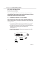
Chapter 3 - EASY INSTALLATION 3.1.2 Connecting Computers to the XRouter Pro When you complete connecting the XRouter Pro to your DSL or cable modem, now you may connect the Macintosh or PC computers in your local area network to the XRouter Pro. Two methods can be implemented for the connection: (1) plugging computers directly into the XRouter Pro, and (2) connecting the XRouter Pro to your LAN hub.
Chapter 3 - EASY INSTALLATION To connect an existing LAN to the XRouter Pro: As an alternative to connecting computers directly into the XRouter Pro’s LAN ports, you can also connect a pre-existing network of the computer to the XRouter Pro by uplinking your network’s central LAN hub to the XRouter Pro’s uplink port. (See Figure 3.1-3) To connect a LAN hub to the XRouter Pro’s uplink port: 1. Set the DIP switch (located on the XRouter Pro’s rear panel just left of the No.
Chapter 3 - EASY INSTALLATION 3.1.3 Connecting the Power Supply To provide your XRouter Pro with power: 1. Plug the power adapter of the XRouter Pro into an AC power outlet. 2. Plug the other end of the power adapter cable into the power receptacle on the rear panel of the unit. 3. The Power LED on the XRouter Pro’s front panel should be lit immediately. 3.2 Software Configuration 3.2.
Chapter 3 - EASY INSTALLATION 3.3 Windows 95/98 TCP/IP Configuration of Computers 1. Double-click the Control Panel icon in My Computer folder. 2. In the Control Panel, double-click the Network icon. The network interface card (installed on your computer) appears along with the network protocol on the Configuration list. 3. Double-click TCP/IP protocol on the list. If TCP/IP does not appear on the list, you must install the TCP/IP protocol first as illustrated in step 4.
Chapter 3 - EASY INSTALLATION d. Follow the instructions on the screen to complete the installation process. Figure 3.3-2 5. After double-clicking the installed TCP/IP protocol, the TCP/IP properties window appears. To automatically assign computer’s TCP/IP, the XRouter Pro’s DHCP server must perform the following functions: a. Click the IP Address tab from the TCP/IP properties window. b. Select the item Obtain IP address automatically.
Chapter 3 - EASY INSTALLATION 3.3.1 Assigning TCP/IP Values Manually If you already have a DHCP server on the network, or if you prefer not to use the XRouter Pro’s DHCP server to assign TCP/IP values automatically, you can input these values manually. To manage computer’s address manually, perform the following functions: (See Figure 3.3-4) 1. Click the IP Address tab from the TCP/IP properties window. 2. In the IP Address field enter “192.168.1.
Chapter 3 - EASY INSTALLATION 3.4 Mac OS TCP/IP Configuration 1. Open the TCP/IP control panel. 2. In the Connect via menu select the Ethernet interface installed on your computer. 3. In the Configure pull-down menu, select Using DHCP Server to allow the built-in DHCP server of the XRouter Pro to assign an IP address and other TCP/IP configuration information to the client automatically. Do this for every client who needs Internet access through the XRouter Pro. (See Figure 3.
Chapter 3 - EASY INSTALLATION To manage computer’s address manually ,perform the following functions: 1. In the Connect via menu select the Ethernet interface installed in your computer. 2. In the Configure menu select Manually. (See Figure 3.4-2) a). In the IP Address field, enter “192.168.1.x” where x is any variable of your choice ranging from 2 - 252. Figure 3.4-2 NOTE: No two computers on LAN is allowed to adopt the same IP address or an IP address confict will occur. b).
Chapter 3 - EASY INSTALLATION 3.4.2 Setting Up the XRouter Pro Through a Web Browser Now that you have completed the configuration of TCP/IP addresses of the client and managing computers, you may begin configuring the XRouter Pro’s Internet settings. This can be done through a standard Web browser (such as Netscape Navigator, Netscape Communicator, or Microsoft Internet Explorer).
Chapter 3 - EASY INSTALLATION 2. Type the XRouter Pro's default IP address (192.168.1.1) in the URL field. This is the area where you would normally enter a Web site address such as “www.macsense.com”. 3. Press Enter. The Username and Password window will then appear. 4. Leave the User name field blank and type “admin“ as the default password for the XRouter Pro. You can change the password through a Web management page later. Click OK. (See Figure 3.4-3) Figure 3.
Chapter 3 - EASY INSTALLATION 5. The OnePage Setup window now appears. Note that this page is divided into two basic sections: Private IP Address, and Public IP Address. Figure 3.4-5 (See Figure 3.4-5) Host Name: This is an optional section. Some ISPs require a host name in order to be recognized by their systems. Your ISP should provide this if it is needed for the systems. Private IP Address: This section can be used for the changes in XRouter Pro’s internal IP Address.
Chapter 3 - EASY INSTALLATION 4. In the Default Gateway IP Address field, enter the information provided by your ISP. Note that it may refer to “Gateway / Router IP Address.” Also note that this number is not the same as the IP Address value that you have entered in step 2. 5. Enter the DNS information provided by your ISP in the Domain Name Server fields. It should provide at least two unique DNS numbers.
Chapter 4 - ADVANCED CONFIGURATION 4.0 ADVANCED CONFIGURATION Please refer to the previous chapter on how to enter the Web Management page of the XRouter Pro. The Advanced Menu contains mini sub-menus including DHCP Settings, Access Control, Virtual Server, Device Admin, Status Monitor, DMZ Host, RIP, Static Routing and PPPoE. 4.1 DHCP Server Settings To alter the starting IP Address range, the number of users are automatically assigned to IP addresses on the LAN.
Chapter 4 - ADVANCED CONFIGURATION 4.2.1 URL Access Setting The URL Access Setting page in the XRouter Pro blocks/allows specific web sites on the LAN when enables. For example, if you choose to stop users on the LAN from accessing the web site “www.yahoo.com”, you would use the Access Control page to block URL access to this site. Figure 4.2-1 To Enable or Disable the URL access feature of the XRouter Pro, select either Enable or Disable from the URL Access Limit button.
Chapter 4 - ADVANCED CONFIGURATION 4.2.2 IP Access Setting The IP Access Setting page in the XRouter Pro can block a user defined IP range from accessing specified ports. This feature is useful when blocking Internet services that you do not desire on your network. (See Figure 4.2-2) Figure 4.2-2 The IP Access Setting sub page contains four sections.
Chapter 4 - ADVANCED CONFIGURATION NOTE: Complete Internet access can be blocked in an IP Range by entering “1” in the first Blocked Port No. field. Blocked Port Range : In this section, you will need to enter the range of ports that need to be blocked. NOTE: The Blocked Port No. and Blocked Port Range section can be operated simultaneously. Below is an example of what you shoud type into the IP Access Setting page when blocking web browsing access to specific range of IP addresses on a network.
Chapter 4 - ADVANCED CONFIGURATION For example, if you set up the TCP port 80 (HTTP: Hypertext Transfer Protocol) to be redirected to the IP address"192.168.1.2" on the Virtual Server setting, the request from the external Internet user via HTTP protocol (i.e. acquire Web page from browser) will be transferred through the XRouter Pro to the computer with the IP address "192.168.1.2" on your local network. (See Figure 4.3-1) Figure 4.
Chapter 4 - ADVANCED CONFIGURATION 4.4 Device Administration This page displays information on the firmware version of the XRouter Pro. You can also change the password, reset the device, disable, or enable external administrative access to the web based configuration of the XRouter Pro, block WAN port scanning and WAN ping responses. (See Figure 4.4-1) Figure 4.4-1 Block WAN Port Scanning: to block or allow external port scanning of the XRouter Pro, select Yes or No and then click Apply.
Chapter 4 - ADVANCED CONFIGURATION 4.5 Status Monitor The status monitor provides information on the working status of the XRouter Pro. It contains the connection information for the WAN side of the router. The term WAN (Wide Area Network) refers to the connection going to the ISP. For a Static or Dynamic IP Address using PPPoE: (See Figure 4.5-1) Figure 4.5-1 DHCP Clients Table: This allows you to view the DHCP clients on the LAN side of the router.
Chapter 4 - ADVANCED CONFIGURATION Statistics: This allows you to view the general traffic on the route, and to display the IP address as well as the number of packets translated for each client. For a Static or Dynamic IP Address without PPPoE: (See FIgure 4.5-2) Figure 4.5-2 DHCP Release: This allows you to release the IP address given by your ISP. DHCP Renew: This allows you to get a new IP address from your ISP. DHCP Clients Table: This allows you to view DHCP clients on the LAN side of the router.
Chapter 4 - ADVANCED CONFIGURATION 4.6 Special APP The Special App is an advanced feature but is not typically required to use the XRouter Pro. This feature allows you to specify a range for incoming ports to be open to computers on the network upon an outgoing trigger port for special application that need two-way communication. For example, if you wanted to allow Quicktime Streaming for the local network, you need to have the proper entries on this page.
Chapter 4 - ADVANCED CONFIGURATION How to Use the Special App Feature To sue this feature, you must know what the outgoing trigger ports are for the given application that needs two-way communications. You must also know the incoming ports that are required fo rhte data that needs to come back into the network. For example, QuickTime typically uses port 554 as the initial outgoing communication port. However, the actual data is then sent back through different incoming ports.
Chapter 4 - ADVANCED CONFIGURATION 4.8 RIP (Routing Information Protocol) This feature allows your XRouter Pro to send and receive RIP packets to/from other routers on the Internet. RIP is a protocol being used by some routers on the Internet. By sending and receiving RIP packets, your XRouter Pro will learn the routes used by neighboring routers. This can increase your its routing performance. The XRouter Pro supports RIP-1, RIP-1 compatible, and RIP-2.
Chapter 4 - ADVANCED CONFIGURATION 4.9 Static Routing The Static routing feature of the XRouter Pro allows the LAN to communicate with another router on the LAN and with their respective LAN segment. By setting up static routes, computers on the XRouter Pro’s immediate LAN may utilize another router’s LAN and XRouter Pro’s LAN simultaneously. See the figure below for the setup process. (See Figure 4.9-1) MIH-130A Internet 192.168.1.3 Router WAN LAN #1 192.168.1.0 Grouter XR100 Power 192.168.2.
Chapter 4 - ADVANCED CONFIGURATION In the example above, PC-1 would have access to LAN#1, LAN#2 and the Internet. Where as, PC-2 would have access to LAN#1 and LAN#2, but not to Internet. In order for PC-2 to have Internet access, a second XRouter Pro or another similarly configurable router would be needed configuration. Static Routing is considered an advanced feature but is not required for basic configuration of the XRouter Pro.
Chapter 4 - ADVANCED CONFIGURATION 4.10 PPPoE Settings Some ISPs require the use of PPPoE for the network connection. When PPPoE is in use, input the username and password provided by your ISP. (See Figure 4.10-1) Figure 4.10-1 Username : Enter the username assigned by your ISP. Password : Enter the password assigned by your ISP. Enter the service name if required. Connect-on-Demand : This feature allows the router to initiate a connection with ISP when a Internet request is made to the XRouter Pro.
Chapter 4 - ADVANCED CONFIGURATION 4.11 Firmware Upgrade Xsense is continually improving the firmware (software programmed on a PROM) in each of its products. The XRouter Pro is shipped with the most up-to-date software available at the time of production. If a firmware upgrade becomes available, it will be posted in the Service and Support section on our Web site. To upgrade the XRouter Pro, you will need the TFTP client and the firmware file named “xxxxx.bin.
Chapter 4 - ADVANCED CONFIGURATION NOTE: Keep the firmware file name “xxxx.bin” unchanged, or the TFTP won’t recognize it. 5. If the upgrade has failed, the Ready/Test LED will be flashing on the XRouter Pro. If this happens, repeat steps 2 - 4 of this procedure.
Chapter 5 - TROUBLESHOOTING 5.0 TROUBLESHOOTING This chapter provides solutions to problems that may occur during the installation and operation of the MIH-130A XRouter Pro. 1. The Link LED is off. -Be sure that all connectors are firmly plugged-in. -Be sure that the power adapter is plugged into an electrical outlet. 2. Can't connect to MIH-130A XRouter Pro via Web browser. -Be sure that the IP address “192.168.1.1” has been correctly entered in the URL field.
APPENDIX A - Specifications APPENDIX A - Specifications Standards Compliance IEEE 802.3 10BASE-T and IEEE 802.3u 100BASE-TX TCP/IP, DHCP, DNS WAN Interface One 10BASE-T RJ-45 port LAN Interface Four 10/100 Mbps RJ-45 ports Web Management Yes LED Display Power, Link/Activity for WAN/LAN ports, Collision/Partition for LAN ports Environment Operation Temperature Storage Temperature Humidity 0°C ~ 45°C (32°F ~ 113°F) -20°C ~ 70°C (-4°F ~ 158°F) 0% ~ 90% Dimensions LxWxH (mm) LxWxH (in.
APPENDIX B - Hardware Description APPENDIX B - Hardware Description Power Green Indicates that there is power to the unit. Ready/Test Red Flashes during boot up WAN Port Link Green Indicates proper connection with Internet / Ethernet. Activity Orange Flashing LED indicates that data packets are flowing through the WAN port.
Rear Panel Description Rear Panel Description Figure A-B-1 LAN Ethernet Ports Four 10/100Mbps Enthernet network (RJ-45) ports used for linking hub/computer in a Local Area Network to the XRouter Pro. WAN Ethernet Port One Wide Area Network port for connecting the XRouter Pro to the Internet via a cable or DSL modem. Reset Button Used for resetting the XRouter Pro’s IP Address information and user password to the factory default settings.
Glossary Glossary Cable Modem A device that connects your PC to a local TV line and receives data at 1.5Mpbs. One of its connections is connected to your PC and the other one is to the cable wall outlet. It attaches a standard 10BASE-T ethernet card to a computer and modulates between digital and analog signals. DHCP DHCP is a protocol for automatic IP configuration. Computers at client premise can get one IP address from DHCP server automatically.
Glossary Gateway An entrance to a network. It associates with both router and switch whereas the router gives direction as data arrives at the gateway and the switch, on the other hand, furnishes its actual path in and out of the gateway. HTTP The Hypertext Transfer Protocal is an application protocol and a set of rules for file exchange on the World Wide Web. IEEE Abbreviation of Institute of Electrical and Electronics Engineers.
Glossary LANs connected this way is called a wide-area network (WAN) MAC Address Short for Media Access Control Address, a hardware address that uniquely identifies each node of a network. In IEEE 802 networks, the Data Link Control (DLC) layer of the OSI Reference Model is divided into two sublayers: the Logical Link Control (LLC) layer and the Media Access Control (MAC) layer. The MAC layer communicate directly with the network media.
Glossary that operates similar to FTP with few resources to run. It uses UDP and requires no login procedures. UDP UDP stands for User Datagram Protocol. It's an user interface between applications and the IP in a network. It has the ability to address a particular appliation process running on a host via a port number without setting up a connetion session. When using UDP, the entire transmission can be sent in one or two UDP datagrams.
180-00325-000